Process and unit for solvent recovery from solvent diluted tailings derived from bitumen froth treatment

a bitumen froth treatment and solvent recovery technology, applied in solvent extraction, extraction purification/separation, separation processes, etc., can solve problems such as short circuiting, affecting recovery and unit reliability, and increasing the time required for diluent separation

Active Publication Date: 2017-06-13
TRUENORTH ENERGY CORP
View PDF360 Cites 5 Cited by
  • Summary
  • Abstract
  • Description
  • Claims
  • Application Information

AI Technical Summary

Benefits of technology

[0074]The invention also provides a method of controlling feed flow rate to a tailings solvent recovery vessel for recovering a solvent from a solvent diluted tailings derived from a bitumen froth treatment process, the method comprising recycling an amount of underflow tailings from the tailings solvent recovery vessel back into the solvent diluted tailings to produce a flow rate controlled tailings feed and to allow sufficient pressure on the flow rate controlled tailings feed to avoid vapour flashing prior to the tailings solvent recovery vessel; and introducing the flow rate controlled tailings feed into the tailings solvent recovery vessel.
[0088]In another optional aspect, the paraffin comprises preferentially retained paraffins that are preferentially retained within asphaltene-bitumen matrices with respect other paraffins of the solvent due to lower diffusivity, and the process comprises providing a residence time of the solvent diluted tailings in the solvent recovery vessel to promote recovery of the preferentially retained paraffins.

Problems solved by technology

However, variations in feed flow and feed temperature result in several challenges that affect recovery and unit reliability.
High feed flows can increase liquid loading on flash column internals which directionally increases the time required for diluent to separate.
In addition, low feed flows can cause “short circuiting” in the flash column when feed does not adequately cover internals and tends to promote depositions of froth treatment tailings minerals, bitumen and asphaltenes on the surfaces of internals.
Furthermore, high feed temperatures can increase the column pressure when water that flashes with diluent exceeds the condensing capacity of the overhead system.
Also, high velocities in the column can encourage unwanted entrainment of particulates that foul the overhead system.
These problems and challenges may owe to a number of factors, including feed properties of the bitumen froth, operating conditions of the froth treatment settling vessels and other parameters of the froth treatment plant.
However, the implications of adding water on performance of flash separation may include several drawbacks.
Limited unit capacity, capital and operational costs associated with centrifuges promoted applying alternate separation equipment for processing diluted bitumen froth.
Using conventional vessel sizing methods, the cost of pressure vessels and associated systems designed for and operated at this high pressure limits the commercial viability of these processes.
However, rapidly setting mineral particles in bitumen froth preclude using a single separation vessel as this material tends to foul the internals of conventional deasphalting vessels.
While low asphaltene rejection maximizes bitumen recovery, the asphaltene content may limit processing options in upgrading operations particularity those based on hydrogen addition.
Furthermore, froth treatment tailings from either naphthenic or paraffinic froth treatment process contain diluent associated with unrecovered bitumen and the cost and environmental impact preclude directly discharging froth treatment tailings to tailings ponds.
However, the investigation identified that increased feed temperatures for the same feed flow did not proportionately translate to increased diluent recovery due to increased vaporization of water.
Stable operation of the column in terms of flash temperature and pressure was found marginally below the boiling point of water for the operating pressure and with small increases in feed enthalpy resulting in upsets as the water can essentially boil.
Firstly, boiling on shed decks results in equipment damage to the extent that the shed decks experience frequent structural failure.
Secondly, the vapour velocity in the column increases, for instance by an order of magnitude, exceeding design guidelines such a set out in “Design Two-Phase Separators within the Right Limits” W. Svrcek, et al.
Chemical Engineering Progress, October 1993, which leads to problems related to entraining solids and bitumen into the overhead system.

Method used


Image

  • Process and unit for solvent recovery from solvent diluted tailings derived from bitumen froth treatment
  • Process and unit for solvent recovery from solvent diluted tailings derived from bitumen froth treatment
  • Process and unit for solvent recovery from solvent diluted tailings derived from bitumen froth treatment

Examples


Embodiment Construction

[0099]According to an embodiment of the present invention, the process and unit allow improved control of feed flow and temperature that set the enthalpy input to the flash column, thereby achieving high solvent recoveries.

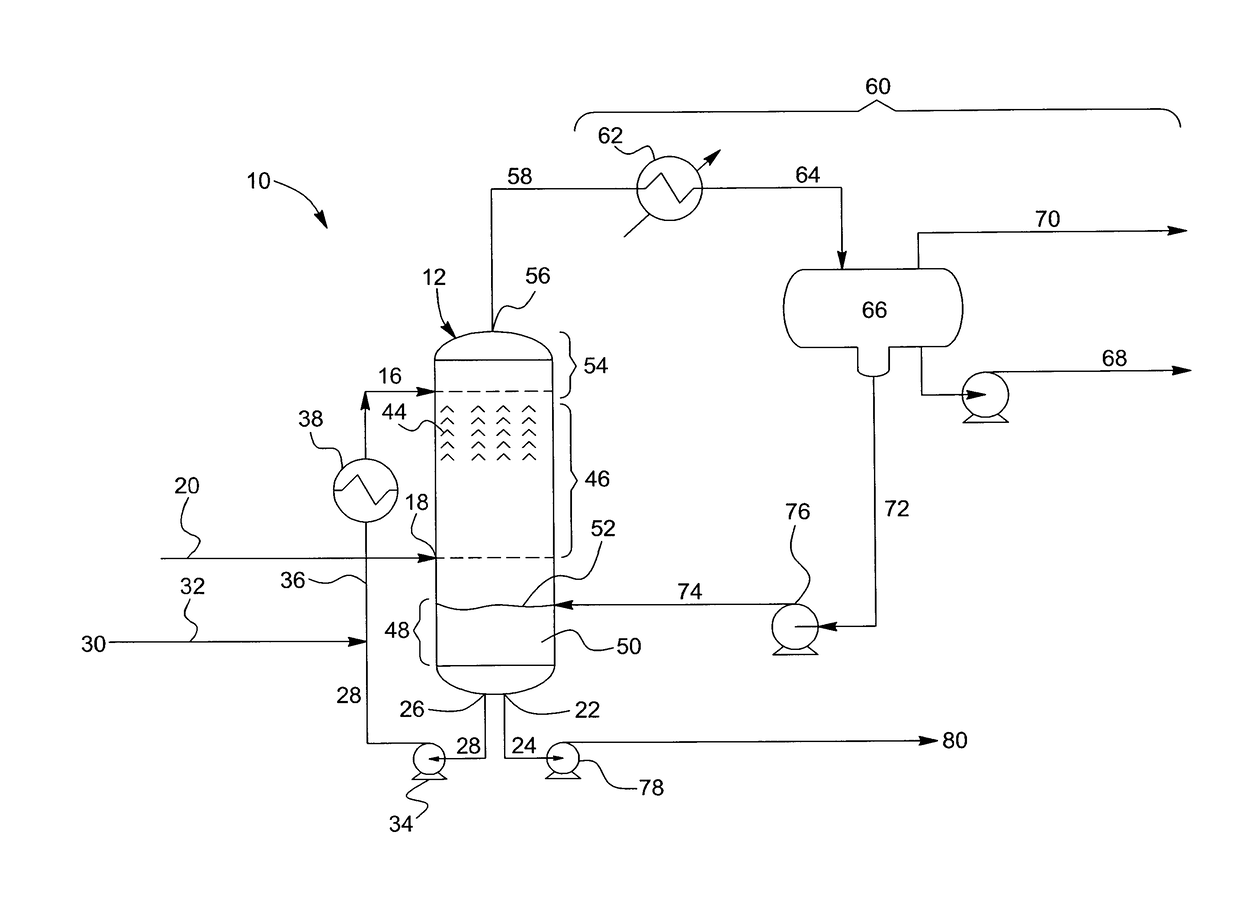
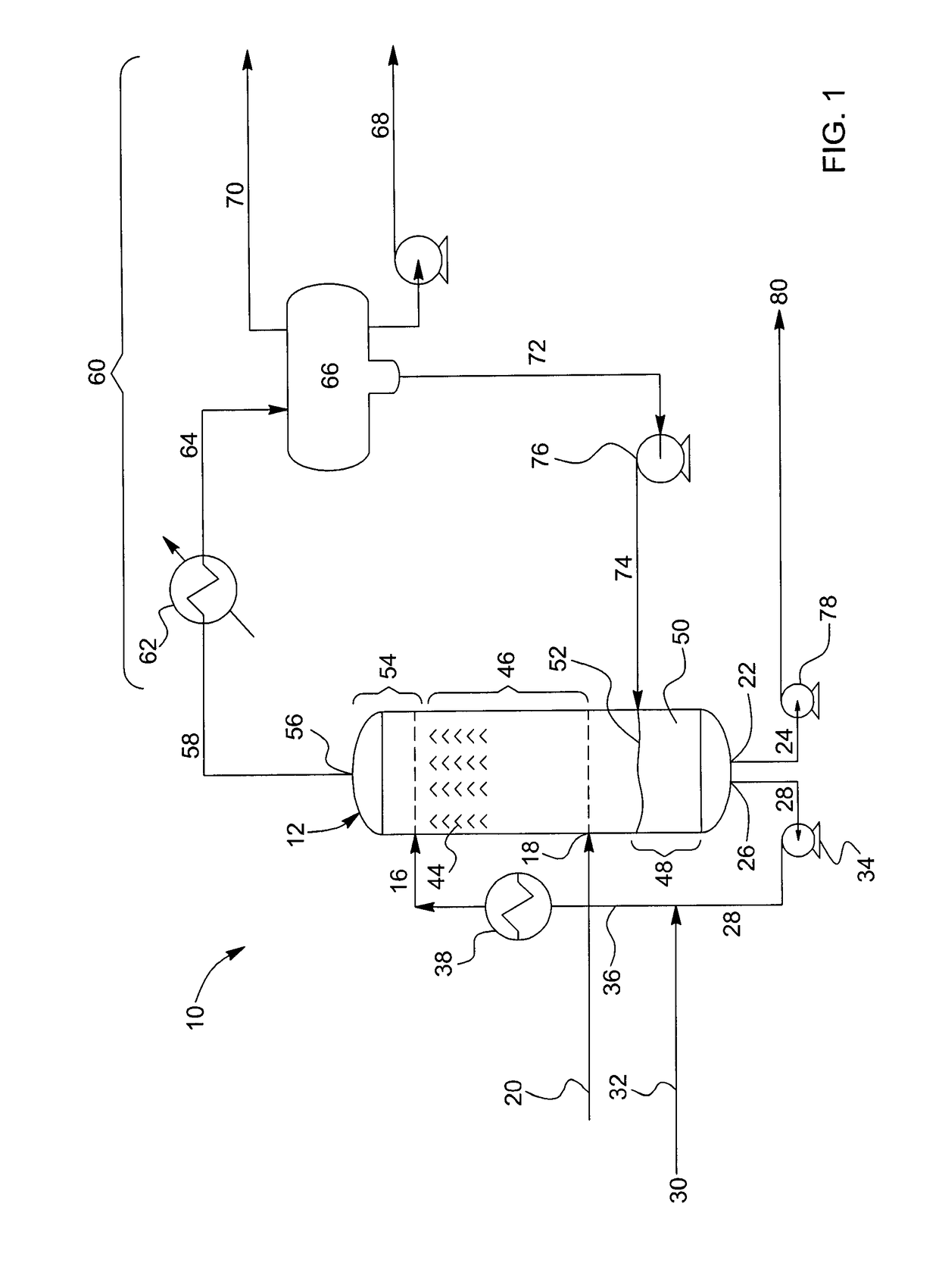
[0100]Referring to FIG. 1, illustrating an embodiment of the present invention, a tailings solvent recovery unit 10 is provided and comprises at least one tailings stripping column 12 having a tailings inlet for providing the tailings feed 16, a steam inlet 18 for providing steam 20, a solvent recovered tailings outlet 22 for withdrawing a portion 24 of the solvent recovered tailings for further treatment or processing, and a recycle outlet 26 for recycling recycled solvent recovered tailings portion 28 of the bottoms.

[0101]Further upstream, froth treatment tailings 30 are provided to the tailings solvent recovery unit10 via a froth treatment tailings line 32. The froth treatment tailings 30 are combined with the recycled solvent recovered tailings 28, which are s...


PUM

PropertyMeasurementUnit
temperatureaaaaaaaaaa

Abstract

A TSRU for recovering solvent from solvent diluted tailings includes a separation apparatus receiving the tailings and producing solvent and solvent recovered tailings. The separation apparatus includes a vessel, a tailings outlet, a solvent outlet, a tailings inlet for supplying a variable flow of the tailings to the vessel and a tailings recycle line connected to the tailings inlet for recycling part of the solvent recovered tailings into the variable flow of the diluted tailings to produce a flow rate controlled feed for introduction into the vessel. A tailings solvent recovery process includes separating the diluted tailings into recovered solvent and solvent recovered tailings, discharging the solvent recovered tailings, and recycling a portion of the solvent recovered tailings back into the variable flow of the diluted tailings. A method of controlling feed flow rate to a tailings solvent recovery vessel is also provided.

Description

FIELD OF THE INVENTION[0001]The present invention relates to the recovery of solvent from solvent diluted tailings derived from a bitumen froth treatment operation.BACKGROUND[0002]In bitumen froth treatment processes, solvent or diluent is added to a bitumen froth to separate a diluted bitumen stream for further processing. In a paraffinic bitumen froth treatment process, for example, bitumen froth derived from oil sands is combined with paraffinic solvent and then supplied to a settling vessel in which a bitumen rich fraction is separated from a bottoms fraction rich in asphaltenes, water, solvent and solids as well as residual amounts of bitumen. This bottoms fraction is often referred to as solvent diluted tailings or froth treatment tailings.[0003]Solvent diluted tailings are preferably treated to recuperate the paraffinic solvent, which is subject to environmental discharge regulations and a valuable commodity, prior to disposal of the resulting solvent recovered tailings conta...

Claims


Application Information

Patent Timeline
Patent Type & Authority Patents(United States)
IPC IPC(8): C07C7/11C10G1/04
CPCC07C7/11C10G1/04C10G1/045C10G2300/4081C10G2300/44
Inventor DUERR, RYANVAN DER MERWE, SHAWNHANN, TOM
Owner TRUENORTH ENERGY CORP
Why Eureka
Try Eureka