Method for mitigating thermal propagation of batteries using heat pipes

a technology of heat pipes and batteries, applied in battery/fuel cell control arrangements, electric devices, lighting and heating apparatus, etc., can solve problems such as fluid pressure increase, and achieve the effects of limiting damage to batteries, increasing temperature uniformity, and protecting against thermal runaway conditions

Active Publication Date: 2017-06-27
GM GLOBAL TECH OPERATIONS LLC
View PDF16 Cites 7 Cited by
  • Summary
  • Abstract
  • Description
  • Claims
  • Application Information

AI Technical Summary

Benefits of technology

[0006]A battery thermal management system that is based on the use of a heat transfer fluid in a passive heat exchange member has the potential to limit damage to a battery under excessively high temperature conditions, thus acting to increase temperature uniformity, as well as protect against thermal runaway conditions. This helps to prolong the life of heat-sensitive components, such as the charge-carrying battery cells that form the building blocks of battery modules and battery packs. In a particular form, a heat pipe (or a system based on a heat pipe) may include a channel in the form of an enclosed pipe or fin and a heat transfer fluid disposed therein which can absorb and release a large amount of latent heat (in some instances up to fifty times higher than sensible heat) during isothermal (i.e., constant temperature) changes of phase. As will likewise be discussed in more detail below, the term “heat pipe” as used in the present context will be understood to include not just traditional tubular-shaped embodiments, but also those of other shapes, such as generally fin-like members where generally thin, shallow flow channels are disposed between opposing, generally parallel plates. The use of heat pipes can help to reduce or eliminate the need for active cooling components such as a fan, blower or pump in forced-air or forced-liquid cooling systems by moving heat from the source to a location below the heat transfer fluid's condensation temperature. This is beneficial in that the heat pipe system can provide the ability to maintain the cell in a desired temperature range without drawing power from the battery or another energy source. Heat pipes in close contact with battery cells can act as a thermal buffer that in turn may result in reduced power fade, reduced capacity fade, improved battery life and durability, reduced warranty costs, improved vehicle range and prevention of thermal runaway.
[0007]According to one aspect of the invention, a battery module is disclosed. The battery module includes one or more battery cells configured to deliver electric current (for example, but not limited to, providing motive power to an automobile) and a heat pipe placed in thermal communication with one or more of the battery cells. The heat pipe includes a container with a heat transfer fluid disposed therein and a pressure control device. The heat transfer fluid absorbs heat at a heat source end of the heat pipe by changing phase from liquid to gas, and then releases the energy when the gas is re-condensed at the heat sink. The pressure control device (also referred to herein as a pressure relief device), container and heat transfer fluid cooperate with one another such that upon attainment of a thermal event within the battery cell or cells, the pressure control device permits fluid communication of the heat transfer fluid now in the gas phase within the container to an ambient environment. In one form, when a thermal event arises, the pressure is sufficient to overcome the pressure control device; this in turn causes release or related activation of the pressure control device, resulting in a void forming in the heat pipe such that the heat transfer fluid disposed inside the pipe can be liberated, such as to the ambient environment, thereby rapidly removing the latent heat present in the heat transfer fluid. In the present context, a thermal event is one where a temperature in excess of a predetermined threshold is present in or around the battery cell or heat pipe. Such excessive temperature typically produce either thermal expansion in exposed materials (in situations where the exposed material is given a chance to expand) or increases in fluid pressure (in situations where the exposed material is not given a chance to expand, such as when contained within a fixed volume). By release of latent heat present in the heat transfer fluid contained within the heat pipe, the battery module can mitigate or eliminate the thermal propagation of heat to adjacent cells or other heat-sensitive components.
[0013]According to yet another aspect of the invention, a method of making a heat pipe for use in a battery module is disclosed. The method includes containing a heat transfer fluid within the heat pipe and arranging it to be in thermal communication with one or more battery cells that make up the module. In this way, a temperature increase in or around the module causes the heat transfer fluid to exert a pressure on the heat pipe; in situations where the temperature increase is high enough, the concomitant pressure increase exerted by the heat transfer fluid on the heat pipe exceeds a predetermined threshold such that a pressure relief device is activated, causing the heat pipe to release at least a portion of the heat transfer fluid. By forming a heat pipe using such a pressure relief device (for example, a rupture disc, relief valve, cap or other calibrated member configured to deploy at a predetermined elevated pressure or temperature), there is reduced risk that subsequent manufacturing steps (especially those that may involve heat exposure to and concomitant overpressure within the heat pipe) will damage or otherwise hamper the operability of the assembled heat pipe. Likewise, the early isolation of the internal compartment of the heat pipe helps to avoid contamination associated with leaving the rupture disc (or a set screw used to hold the rupture disc in place during heat pipe manufacture) off.

Problems solved by technology

Such excessive temperature typically produce either thermal expansion in exposed materials (in situations where the exposed material is given a chance to expand) or increases in fluid pressure (in situations where the exposed material is not given a chance to expand, such as when contained within a fixed volume).

Method used


Image

  • Method for mitigating thermal propagation of batteries using heat pipes
  • Method for mitigating thermal propagation of batteries using heat pipes
  • Method for mitigating thermal propagation of batteries using heat pipes

Examples


Embodiment Construction

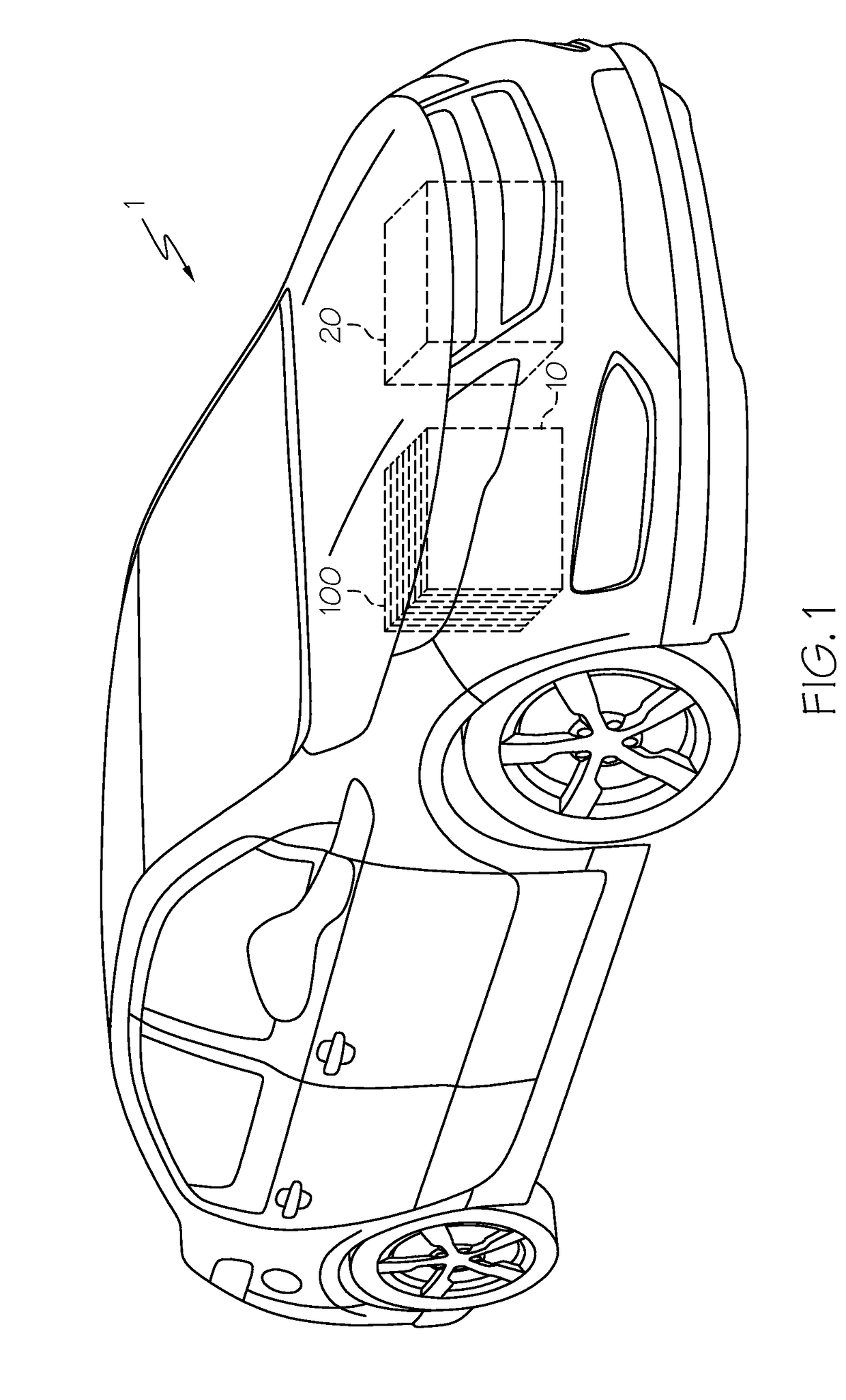
[0023]Referring first to FIG. 1, a vehicle 1 includes a hybrid propulsion system in the form of a battery pack 10 and a conventional ICE 20. As mentioned above, such a vehicle is known as an HEV. Battery pack 10 employs numerous battery modules 100 that are typically arranged in a repeating array as shown. In one typical example, battery pack 1 may about two hundred individual battery cells (to be discussed in more detail below), although it will be appreciated by those skilled in the art that additional or fewer cells may be needed, depending on the power required. It will be further appreciated by those skilled in the art that vehicle 1 may not require an ICE 20; in such case, rather than being an HEV, it is a EV; either form is within the scope of the present invention.

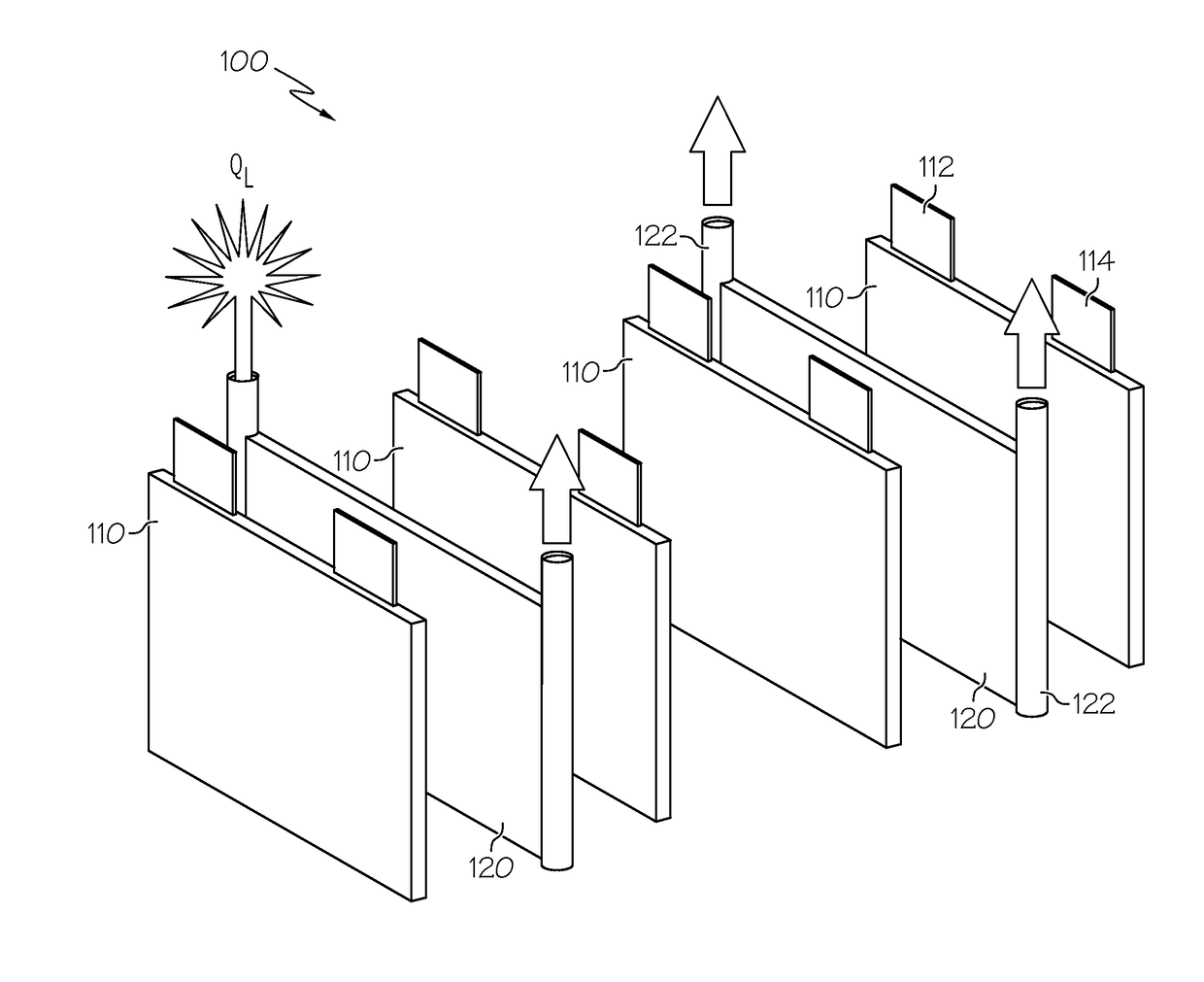
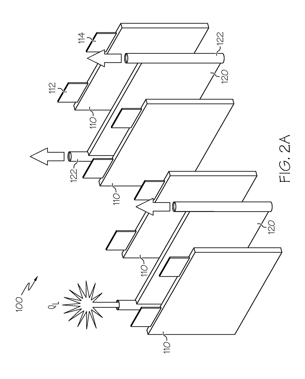
[0024]Referring next to FIG. 2A, an exploded view depicting significant portions of a battery module 100 with passive thermal propagation mitigation features is shown, according to one embodiment of the invention. ...


PUM

PropertyMeasurementUnit
temperaturesaaaaaaaaaa

Abstract

A battery module with one or more battery cells and a heat exchange member placed in thermal communication with the battery cell, and a method of making a heat pipe system from the heat exchange member. The heat exchange member includes a container with a heat transfer fluid disposed therein. In one form, the heat transfer fluid is capable of going through a phase change as a way to absorb at least a portion of heat present in or generated by battery cell. A pressure control device cooperates with the container and heat transfer fluid such that upon attainment of a predetermined thermal event within the battery cell, the pressure control device permits liberation of at least a portion of the heat transfer fluid to an ambient environment, thereby relieving pressure on the container and removing some of the excess heat caused by the thermal event.

Description

BACKGROUND OF THE INVENTION[0001]This invention relates generally to passive thermal management of batteries and portions thereof, and more particularly to the use of a heat pipe with a pressure relief device to reduce the risk of thermal propagation of heat generated within the battery during a thermal event.[0002]Lithium-ion and related batteries, collectively known as a rechargeable energy storage system (RESS), are being used in automotive applications as a way to supplement, in the case of hybrid electric vehicles (HEVs), or supplant, in the case of purely electric vehicles (EVs), conventional internal combustion engines (ICEs). The ability to passively store energy from stationary and portable sources, as well as from recaptured kinetic energy provided by the vehicle and its components, makes batteries ideal to serve as part of a propulsion system for cars, trucks, buses, motorcycles and related vehicular platforms. In the present context, a cell is a single electrochemical un...

Claims


Application Information

Patent Timeline
Patent Type & Authority Patents(United States)
IPC IPC(8): F28D15/02B60L3/00B60L11/18F28D15/06H01M10/625H01M10/647H01M10/6552H01M10/6555H01M10/613H01M10/6562
CPCF28D15/0283B60L3/0046B60L11/1874B60L11/1875B60L11/1877B60L11/1879F28D15/0233F28D15/06H01M10/613H01M10/625H01M10/647H01M10/6552H01M10/6555B60L2240/545F28F2265/12H01M10/6562Y02T10/705Y02T10/7005Y02T90/16Y10T29/49353B60L58/27B60L50/66B60L50/64B60L58/18B60L58/26Y02T10/70Y02E60/10
Inventor TIMMONS, ADAM T.CHRISTIAN, BENJAMIN R.
Owner GM GLOBAL TECH OPERATIONS LLC
Why Eureka
Try Eureka