Illumination system for lithographic projection exposure step-and-scan apparatus

a technology of lithographic projection and exposure step and scan, which is applied in the direction of microlithography exposure apparatus, printers, instruments, etc., can solve the problems of system requiring a lower scanning speed and requiring up to micron even submicron precision during scanning, so as to reduce the difficulty of lens processing and facilitate implementation

Active Publication Date: 2017-07-18
BEIJING GUOWANG OPTICAL TECH CO LTD
View PDF8 Cites 0 Cited by
  • Summary
  • Abstract
  • Description
  • Claims
  • Application Information

AI Technical Summary

Benefits of technology

[0007]The present invention overcomes the disadvantages of the current technology and provides an illumination system for a lithographic projection exposure step-and-scan apparatus that reduces the difficulty of lens processing, the requirements of slit scanning accuracy and speed, and therefore is easier to be implemented.
[0012]1. To improve the illumination uniformity in the illumination system for lithography apparatus and correct various aberrations, aspheric lens is often used. The clear aperture of the lens in the illumination system in U.S. Pat. No. 8,004,656 B2 is about hundreds of millimeters, In comparison, the clear aperture of single lens in the present invention is between several millimeters to several centimeters, thus, processing smaller aspheric lens is more easier so the illumination system of the present invention reduces the processing difficulty and is easier to implement.

Problems solved by technology

Compared with U.S. Pat. No. 8,004,656 B2, the system requires a lower scanning speed, but because the size of arrays is small, it needs up to micron even submicron precision during scanning.

Method used


Image

  • Illumination system for lithographic projection exposure step-and-scan apparatus
  • Illumination system for lithographic projection exposure step-and-scan apparatus
  • Illumination system for lithographic projection exposure step-and-scan apparatus

Examples


first embodiment

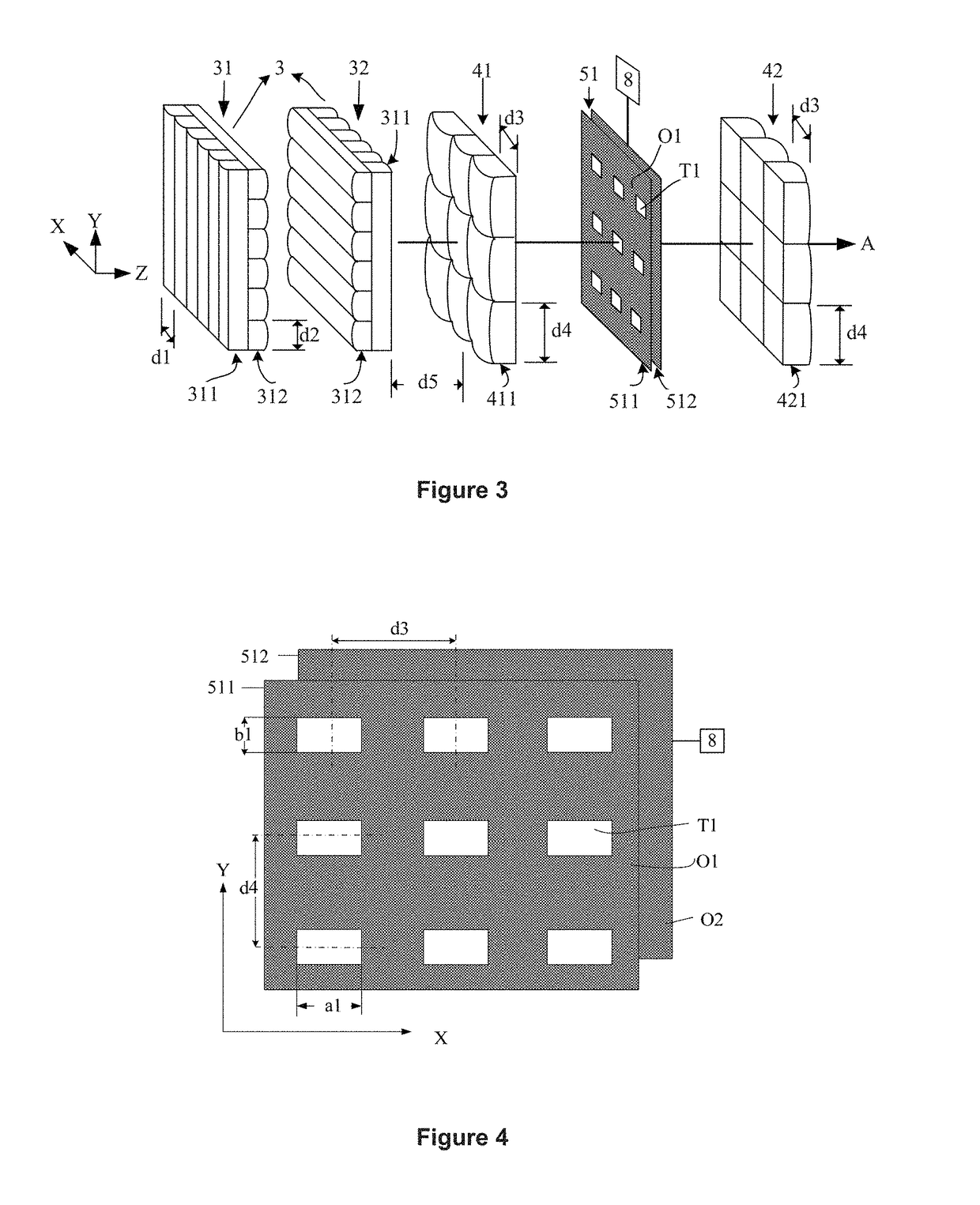
[0026]As shown in FIG. 3, in the present invention, the field defining unit is composed of the first microlens array 31 and the second microlens array 32. The front surface of the first microlens array 31 has micro cylindrical lens 311 with generatrix along Y direction, these micro cylindrical lens are arranged along the X direction with cycle d1. The rear surface of the first microlens array 31 has micro cylindrical lens 312 with generatrix along X direction, these micro cylindrical lens are arranged along the Y direction with cycle d2. The front surface of the second microlens array 32 and the rear surface of the first microlens array 31 are identical, the rear surface of the second microlens array 32 and the front surface of the first microlens array 31 are identical. The first lens array 41 is composed with several identical lens 411, these lens are two-dimensional periodically arranged with cycle d3 along x direction and cycle d4 along y direction. The second lens array 42 is c...

second embodiment

[0029]As shown in FIG. 5, in the structure of the field defining unit to the second lens array according to the present invention, the field defining unit comprises the microlens array 31 and the microlens array 32. The front surface of the first microlens array 31 has micro cylindrical lens 311 with generatrix along Y direction, these micro cylindrical lens are arranged along the X direction with cycle d1. The rear surface of the first microlens array 31 has micro cylindrical lens 312 with generatrix along X direction, these micro cylindrical lens are arranged along the Y direction with cycle d2. The front surface of the second microlens array 32 and the rear surface of the first microlens array 31 are identical, the rear surface of the second microlens array 32 and the front surface of the first microlens array 31 are identical. The first lens array 41 comprises several same lens 411, these lens are periodically arranged with cycle d4 in the y direction. The clear aperture of the ...

third embodiment

[0031]As shown in FIG. 7, in the field defining unit to the second lens array according to the present invention, the microlens array 31 comprises the micro lens 31 and the micro lens 32. The front surface of the first microlens array 31 is micro cylindrical lens 311 with generatrix along Y direction periodically arranged along the X-direction with cycle d1. The rear surface is micro cylindrical lens 312 with generatrix along X direction periodically arranged along the Y-direction with cycle d2. The front surface of the second microlens array 32 and the rear surface of the first microlens array 31 are identical, while the rear surface of the second microlens array 32 and the front surface of the first microlens array 31 are identical. The first lens array 41 has a single lens 411 periodically arranged with cycle d3 in the y direction. The clear aperture of the first lens array 41 is twice larger than the clear aperture of the curved surface of micro-cylindrical lens in field definin...


PUM

PropertyMeasurementUnit
diameteraaaaaaaaaa
speedaaaaaaaaaa
distance d5aaaaaaaaaa

Abstract

Illumination system for a lithographic projection exposure step-and-scan apparatus comprising a light source, a pupil shaping unit, a field defining unit, a first lens array, a first slit array, a second lens array, a third lens array, a second slit array, a fourth lens array, a condenser lens, and a scanning drive unit sequentially arranged along the light beam propagation direction. The illumination system reduces requirements on lens processing, slit scanning speed, and slit scanning precision, therefore may be implemented more easily.

Description

CROSS-REFERENCE TO RELATED APPLICATIONS[0001]The subject application is a continuation of PCT / CN2013 / 001005 filed on Aug. 26, 2013, which claims priority on Chinese patent application 201310270245.1 filed on Jul. 1, 2013 in China. The contents and subject matter of the PCT and Chinese priority applications are incorporated herein by reference.TECHNICAL FIELD[0002]The present invention relates to lithographic projection exposure apparatus, especially the illumination system for a lithographic projection exposure step-and-scan apparatus.BACKGROUND OF THE INVENTION[0003]Optical lithography is an optical exposure process which transfers the pattern of the mask plate onto the silicon wafer. According to different exposure methods, Optical lithography is divided into contact lithography, proximity lithography, step-and-repeat projection lithography, and step-and-scan projection lithography. Step-and-scan projection lithography may effectively increase the chip productivity, therefore it h...

Claims


Application Information

Patent Timeline
Patent Type & Authority Patents(United States)
IPC IPC(8): G03B27/54G03F7/20
CPCG03F7/7015G03F7/70058G03F7/70066G03F7/70075
Inventor ZENG, AIJUNCHEN, LIQUNFANG, RUIFANGHUANG, HUIJIE
Owner BEIJING GUOWANG OPTICAL TECH CO LTD
Why Eureka
Try Eureka