Method and system for engine control

a technology of engine cranking and control system, which is applied in the direction of electrical control, engine starters, hybrid vehicles, etc., can solve the problems of degrading exhaust emissions, insufficient time for mixing of injected fuel and air in the cylinder, and generating more particulate matter (pm) emissions, etc., to achieve better enabling the charge cooling effect of injected fuel, high fuel efficiency, and high power outpu

Active Publication Date: 2017-09-12
FORD GLOBAL TECH LLC
View PDF42 Cites 5 Cited by
  • Summary
  • Abstract
  • Description
  • Claims
  • Application Information

AI Technical Summary

Benefits of technology

[0002]Engines may be configured with direct fuel injectors that inject fuel directly into a combustion cylinder (direct injection), and / or with port fuel injectors that inject fuel into a cylinder port (port fuel injection). Direct injection allows higher fuel efficiency and higher power output to be achieved in addition to better enabling the charge cooling effect of the injected fuel.
[0004]Engine testing data indicates that PM emissions can be reduced by increasing engine temperature. Thus, an electric engine heater may be included in some engine systems. For example, as shown by Vigild et al. in US 20120291762, an intake heater is operated during DFSO conditions when engine fueling is deactivated. By heating air pumped to engine cylinders, the engine can be sufficiently heated to reduce soot emissions.
[0006]Some of the above issues may be addressed by taking advantage of various combinations of engine compression heating as well as individual cylinder compression stroke heating. One example method includes, while propelling a hybrid vehicle via motor torque, rotating an electrically-actuated intake compressor with an intake throttle closed and an EGR valve open until a piston temperature is higher than a threshold. Another example method includes, while propelling a hybrid vehicle via only motor torque, rotating an engine unfueled via the motor torque at lower than engine cranking speed while operating an exhaust heater coupled to an exhaust catalyst and while holding an EGR valve open and an intake throttle closed to recirculate heated aircharge through the engine. Still other combinations may be used in various heating modes. In this way, cylinder heating may be expedited before an engine is restarted.
[0007]As an example, while operating a hybrid vehicle in an electric mode, before an imminent engine start and in response to cylinder piston temperatures being not sufficiently hot, the engine may be slowly cranked, unfueled, via the hybrid vehicle's motor / generator to heat the engine cylinders. In one example, the slow cranking may be initiated at least 2-3 minutes before an engine start. The engine may be rotated slowly at lower than an engine cranking speed, such as at 10-30 rpm. During the slow engine rotation, each cylinder may be sequentially passed through a cylinder compression stroke where heat is transferred from the compressed air to the cylinder walls, head and piston. Even though the absolute amount of heat transferred to the engine may be low, the heat is transferred directly to a location where the heating enables a reduction is soot emissions when engine fueling is resumed. While rotating the engine, an intake throttle may be held closed while an EGR valve is held open so that the heated aircharge is pumped in a loop, further improving cylinder heat transfer. Optionally, one or more of an electric intake heater and an electric exhaust catalyst heater may be concurrently operated to further raise the temperature of the charge being circulated through the engine cylinders. In addition to raising cylinder temperature, the slow engine rotation enables a fuel rail pressure to be raised. Once the cylinder temperatures are sufficiently hot, such as when piston temperature is higher than a threshold, and if engine restart conditions exist, the engine may be rotated faster during cranking and engine fueling may be resumed.
[0009]In this way, by operating an electrically-actuated intake compressor prior to an engine restart, compressor rotation may be used to compress aircharge, thereby generating heat. By rotating the compressor with a compressor recirculation valve open, heat may be rejected from the compressed air at a downstream charge air cooler. By concurrently opening an EGR valve and closing an intake throttle, the heated aircharge can be looped across the engine. In addition, aircharge heating can be enhanced through the use of an intake or exhaust heater. By additionally or optionally slowly rotating the engine, unfueled, via motor torque, the pumped air can also be flowed through one or more cylinders, thereby warming the cylinders prior to an engine restart. In addition, compression stroke heating may be used to heat the cylinders. By pre-heating the engine, particulate emissions from the engine can be reduced, particularly during an engine cold-start. In addition, fuel pressure can be raised to an optimum value for the start, improving fuel injector spray characteristics during the restart. Overall, cold-start emissions can be improved.

Problems solved by technology

Direct injected engines, however, can generate more particulate matter (PM) emissions (or soot) due to diffuse flame propagation wherein fuel may not adequately mix with air prior to combustion.
Since direct injection, by nature, is a relatively late fuel injection, there may be insufficient time for mixing of the injected fuel with air in the cylinder.
Consequently, there may be pockets of rich combustion that may generate soot locally, degrading exhaust emissions.
In particular, until the combustion chamber is fully warmed up, soot is generated due to poor fuel evaporation caused by poor fuel injector spray characteristics at low fuel rail pressure and / or fuel impacting the cold metal surfaces of the combustion chamber.
However, the inventors have identified potential issues with such an approach.
As one example, due to the limited time available prior to an engine start, sufficient heating may not be possible.
Likewise, due to the limited power availability on the vehicle, as well as the large engine mass, the available heating may not be sufficient.
As such, the power required for sufficient engine heating may be higher, leading to poor fuel economy.

Method used


Image

  • Method and system for engine control
  • Method and system for engine control
  • Method and system for engine control

Examples


Embodiment Construction

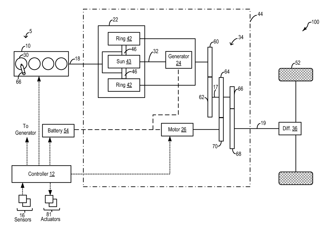
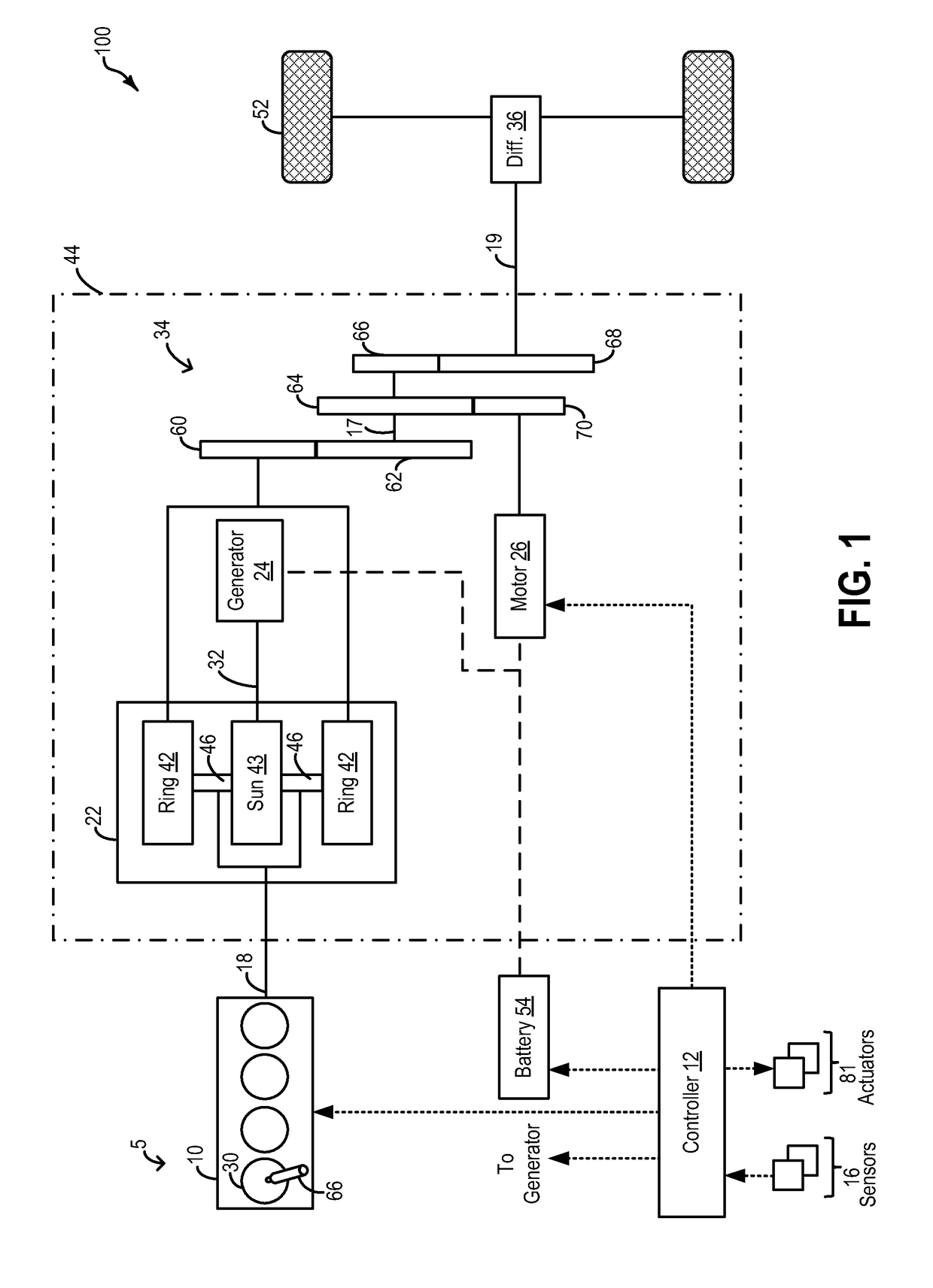
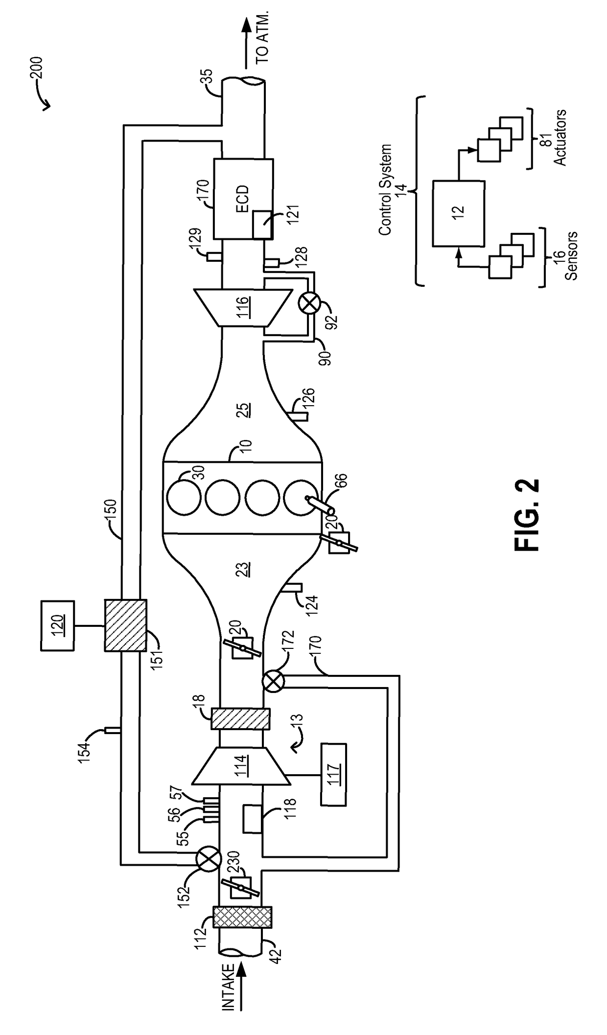
[0019]The following description relates to systems and methods for reducing particulate emissions from an engine, such as the engine system of FIGS. 2-3, coupled in a hybrid vehicle system, such as the plug-in hybrid electric vehicle of FIG. 1. A controller may be configured to perform a routine, such as the example routines of FIGS. 4-5, to rotate the engine, unfueled, during vehicle operation using motor torque, so as to transfer heated generated from compressing air in a compression stroke (FIG. 7) to heat engine combustion chambers while also raising fuel pressure. Additionally, the controller may rotate an electrically-actuated compressor of the engine system to heat the engine via compressor energy. The controller may use various combinations of compression heating, as listed in the table of FIG. 6. An example engine heating operation is shown at FIG. 8. In this way, engine particulate emissions can be reduced, particularly during cold-starts.

[0020]FIG. 1 depicts a hybrid prop...


PUM


Abstract

Methods and systems are provided for using compression heating to heat a cylinder piston before cylinder combustion is resumed. Cylinder heating is achieved using combinations of slow unfueled engine rotation where the engine cylinders are heated via compression stroke heating, and slow compressor rotation where the cylinders are heated via compression heating. One or more intake or exhaust heaters may be concurrently operated to expedite cylinder heating.

Description

FIELD[0001]The present application relates to methods and systems for controlling engine cranking in a hybrid vehicle system.BACKGROUND AND SUMMARY[0002]Engines may be configured with direct fuel injectors that inject fuel directly into a combustion cylinder (direct injection), and / or with port fuel injectors that inject fuel into a cylinder port (port fuel injection). Direct injection allows higher fuel efficiency and higher power output to be achieved in addition to better enabling the charge cooling effect of the injected fuel.[0003]Direct injected engines, however, can generate more particulate matter (PM) emissions (or soot) due to diffuse flame propagation wherein fuel may not adequately mix with air prior to combustion. Since direct injection, by nature, is a relatively late fuel injection, there may be insufficient time for mixing of the injected fuel with air in the cylinder. In some operating conditions, the liquid fuel droplet may directly impinge on the combustion surfac...

Claims


Application Information

Patent Timeline
Patent Type & Authority Patents(United States)
IPC IPC(8): B60K1/02F02N19/04F02D23/02F02D21/04F02D13/02B60W10/06F02N19/00F02D41/00
CPCF02D13/02B60W10/06F02D21/04F02D23/02F02N19/04B60W2710/06B60W2710/0616B60W2710/0638B60W2710/0644F02D41/0002F02D41/0055F02D2250/24F02N19/004Y10S903/902Y10T477/23B60Y2400/442B60Y2300/437B60W10/08B60W30/192B60W2710/0605B60W2710/0633B60W2710/0688B60W2710/0694B60Y2300/474B60W20/40B60Y2400/435B60Y2300/434B60W20/16Y02T10/40Y02T10/62
Inventor ULREY, JOSEPH NORMANROLLINGER, JOHN ERICSHELBY, MICHAEL HOWARDYI, JIANWEN JAMES
Owner FORD GLOBAL TECH LLC
Why Eureka
Try Eureka