
Dynamic aperture holography

a dynamic aperture and holography technology, applied in the field of holographic data storage, can solve the problem of limiting the extent to which multilayer techniques can be exploited to increase the density of storage, and achieve the effect of increasing the density of data storag

Inactive Publication Date: 2017-09-12
AKONIA HOLOGRAPHICS
View PDF13 Cites 6 Cited by
  • Summary
  • Abstract
  • Description
  • Claims
  • Application Information

AI Technical Summary

Benefits of technology

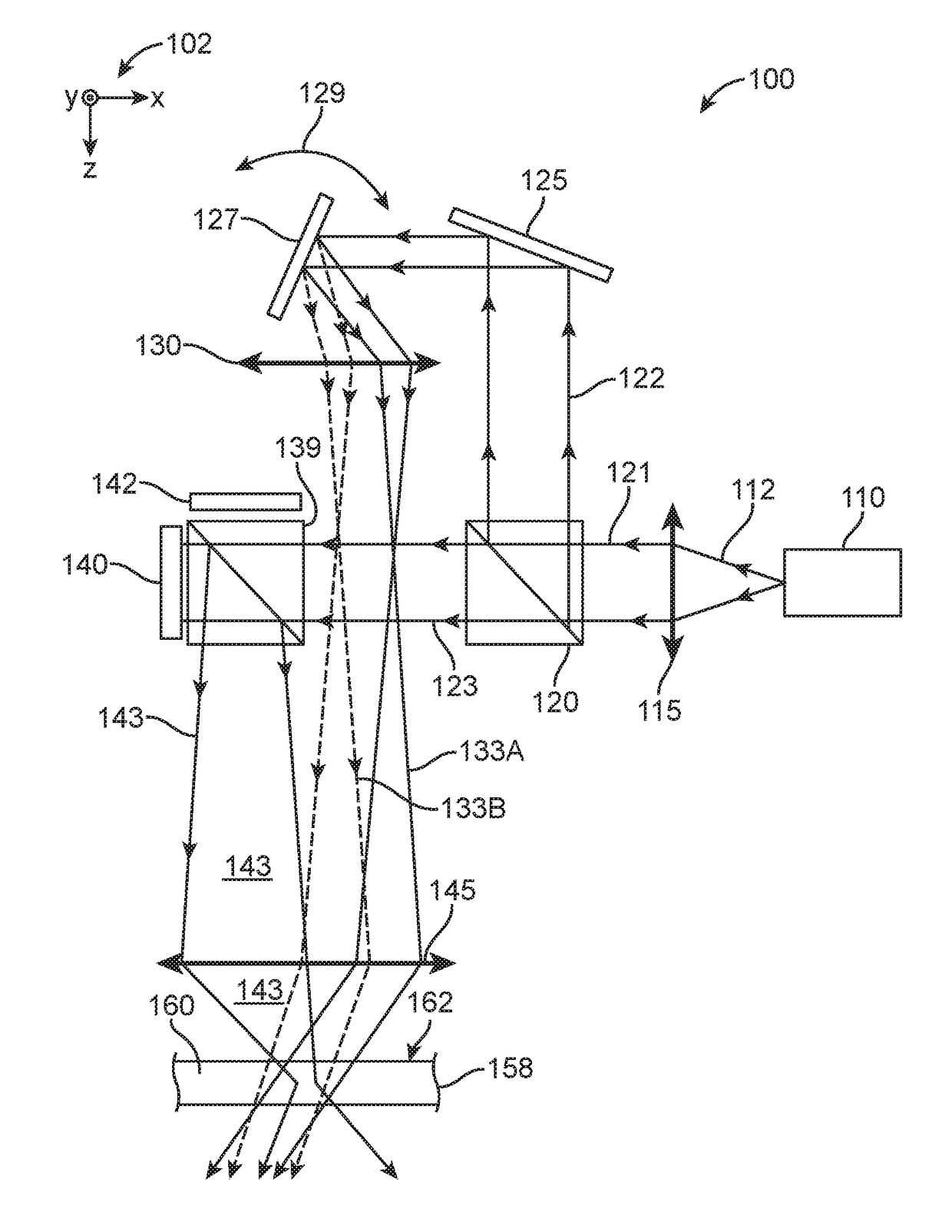
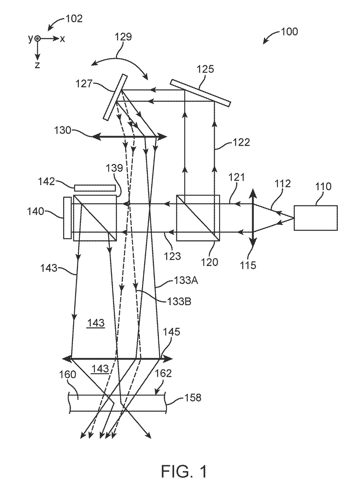
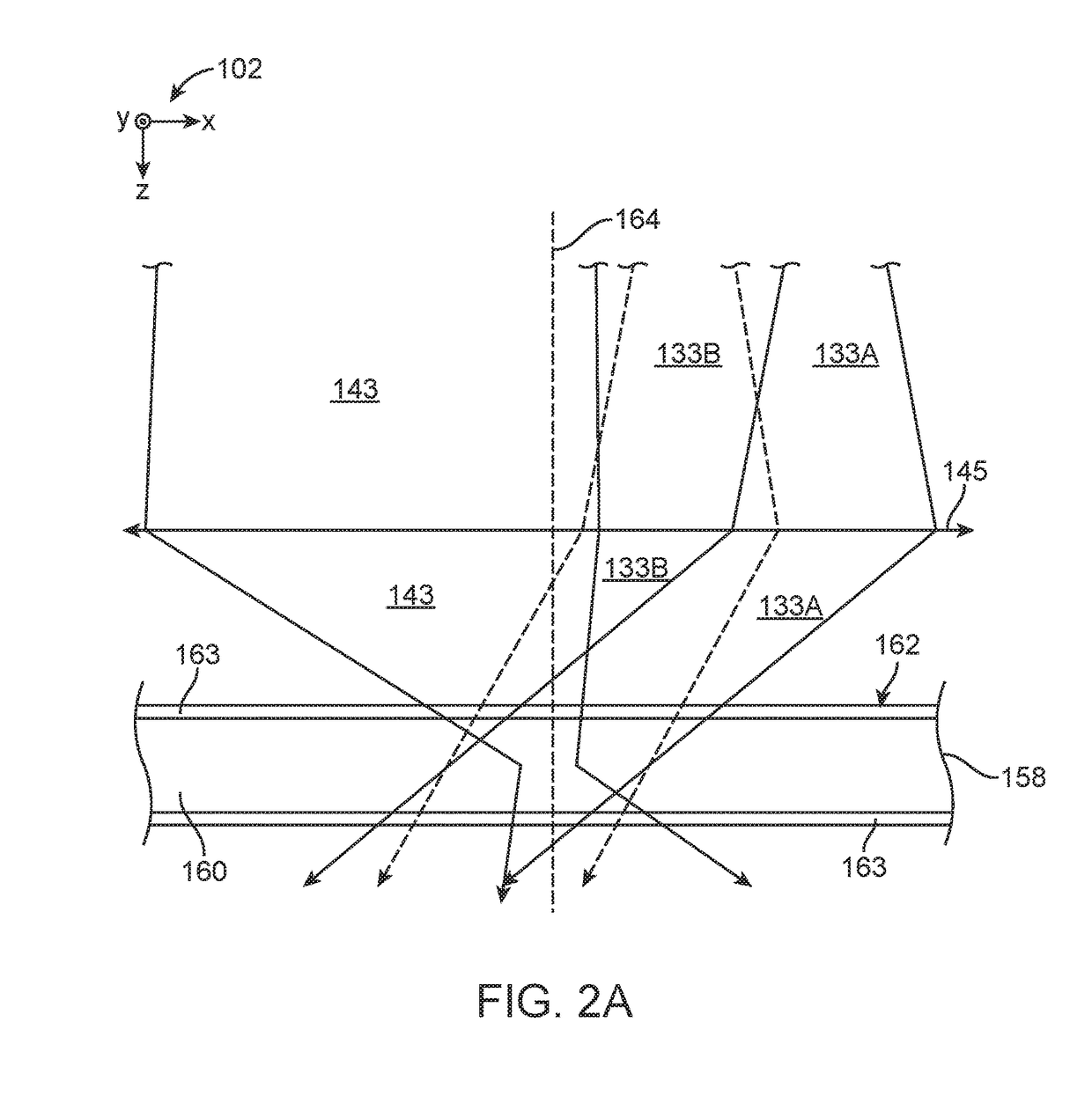
This patent describes a way to capture multiple holograms using a larger range of reference beam angular apertures. This allows for more data to be stored in a holographic recording medium, resulting in greater density of data storage. The technique is well-suited for use with monocular objective lens architecture. The technical effect is improved holographic recording using multiple signal beam angular apertures.

Problems solved by technology

Variations in which multiple layers of stored data reside beneath a storage media surface are known, but light scatter caused by the multiple layers usually limits the extent to which multilayer techniques can be exploited to increase storage density in non-holographic optical data storage.

Method used


Image

  • Dynamic aperture holography
  • Dynamic aperture holography
  • Dynamic aperture holography

Examples


first embodiment

A First Embodiment Dynamic Aperture Holographic System

[0075]A first embodiment dynamic aperture holographic system 200 is illustrated in FIGS. 3A and 3B. A variation of the first embodiment system 200 is illustrated in FIG. 3C. The first embodiment dynamic aperture holographic system 200 includes monocular architecture, but some other embodiments of dynamic aperture holographic systems do not include monocular architecture. The first embodiment system 200 is configured to readily perform dynamic aperture holography by recording multiple holograms using multiple signal beams, wherein the multiple signal beams have multiple signal beam angular apertures that differ from each other. As shown in FIG. 3A, the first embodiment system 200 comprises light source 210 configured to produce light beam 212, which passes through collimating lens 215 to produce a collimated light beam 221.

[0076]The light source 210 is typically, but not necessarily, an external cavity, single-mode, tunable diode ...

second embodiment

A Second Embodiment Dynamic Aperture Holographic System

[0118]A second embodiment dynamic aperture holographic system 400, illustrated in FIG. 10, includes monocular architecture and is configured to readily perform dynamic aperture holography. The second embodiment system 400 includes an external cavity diode laser 410 configured to produce a coherent light beam 412, which passes through collimating lens 415 to produce a collimated light beam 421. The collimated light beam 421 propagates to mirror galvanometer 427, whereupon it is directed as a reference beam 433 through reference beam converging lens 451. The mirror galvanometer 427 is configured to rotate through a defined range, the rotation being illustrated by rotation arrow 429. The rotation of the mirror galvanometer 427 thus directs the reference beam 433 through the reference beam converging lens 451 at various angles. Reference beam angular aperture is thus adjusted using the mirror galvanometer 427.

[0119]The reference bea...


PUM


Abstract

Methods and systems for performing dynamic aperture holography are described. Examples include a method of recording multiple holograms in a photosensitive recording medium, where multiple signal beam angular apertures used to record the multiple holograms differ from each other. The multiple signal beam angular apertures can facilitate using a larger range of reference beam angular apertures. The multiple holograms are typically multiplexed, and examples of dynamic aperture holography enable packing the multiplexed holograms more densely in the recording medium. Some dynamic aperture holography systems include monocular objective lens architecture.

Description

CROSS-REFERENCE TO RELATED APPLICATIONS[0001]The present application claims priority to U.S. patent application No. 61 / 755,893, filed Jan. 23, 2013, and U.S. patent application Ser. No. 13 / 875,071, filed May 1, 2013. Applications U.S. 61 / 755,893 and U.S. Ser. No. 13 / 875,071, the entire disclosures of are hereby incorporated by reference, have the same inventors as the present application.FIELD OF THE INVENTION[0002]The present invention relates generally to holographic data storage.BACKGROUND[0003]High density data storage is in great demand, and holographic techniques enable storing data at higher density relative to other data storage techniques. Holographic data storage also facilitates faster transfer rate for recording and retrieving data compared to other optical storage techniques and to magnetic tape based data storage.[0004]Holographic data storage generally includes modulating a light beam to contain data, with the modulated light beam often referred to as a signal beam. T...

Claims


Application Information

Patent Timeline
IPC IPC(8): G03H1/26G11B7/0065G03H1/02G11B7/007G11B7/1381
CPCG03H1/265G03H1/0248G03H1/2645G11B7/0065G11B7/00772G11B7/1381G03H2001/267
Inventor AYRES, MARK R.ANDERSON, KENNETH E.ASKHAM, FREDRIC R.SISSOM, BRADLEY J.
Owner AKONIA HOLOGRAPHICS
Learn More