
Charger for vehicles

a technology for charging devices and vehicles, applied in the field of charging devices for vehicles, can solve the problems of increasing the number of output capacitors required, and reducing the efficiency of the charger, so as to reduce the ripple current, and facilitate the adjustment of the magnetizing inductance

Active Publication Date: 2017-10-17
HYUNDAI MOTOR CO LTD
View PDF41 Cites 13 Cited by
  • Summary
  • Abstract
  • Description
  • Claims
  • Application Information

AI Technical Summary

Benefits of technology

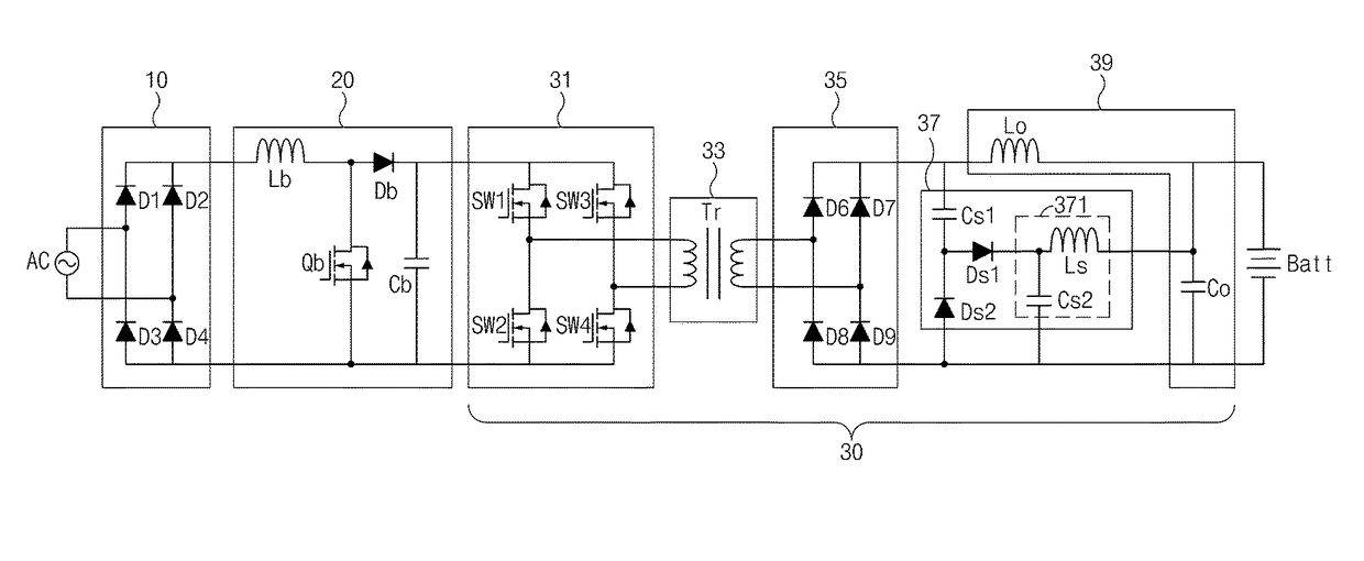
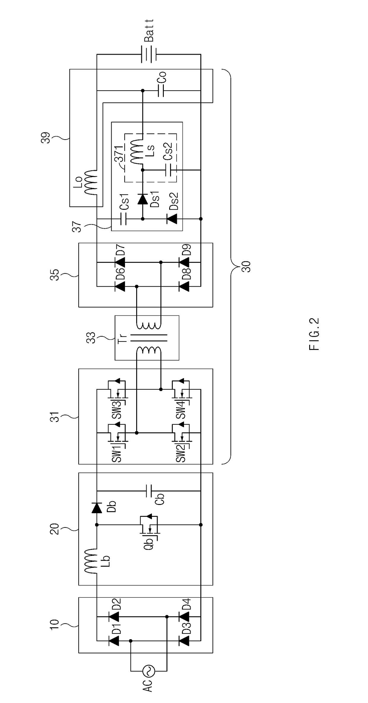
The present invention provides a charger for electric vehicles that reduces ripple current charging an output capacitor using a filter circuit composed of a capacitor and inductor in a snubber circuit of a DC / DC converter. This reduces conducting loss and increases efficiency of the DC / DC converter. Additionally, the invention adjusts the magnetizing inductance by using a gap in the core of a transformer to minimize switching loss and maximize output efficiency. The charger is capable of reducing noise, decreasing conducting loss, and improving efficiency without additional components. This invention is useful for reducing the cost of charging high voltage batteries of electric vehicles.

Problems solved by technology

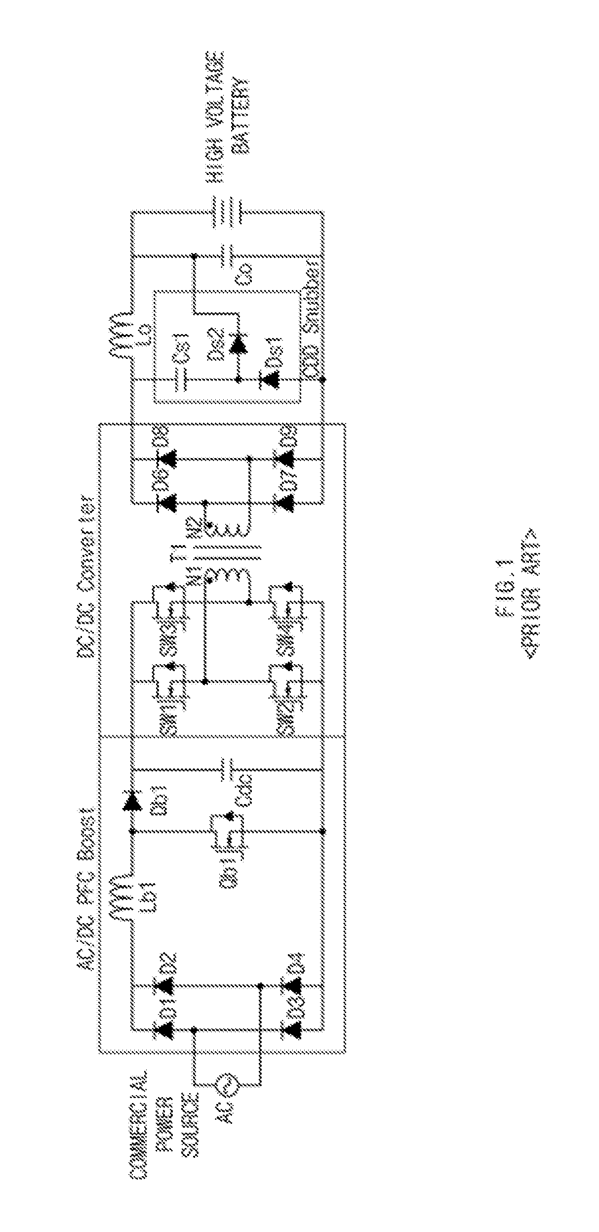
Thus, the prior art has the disadvantage that an increased number of the output capacitors are required to facilitate suppressing the performance degradation and the ripple current.
Additionally, a switching loss exists and the efficiency of the charger is reduced due to the freewheeling current of the transformer T1 being reduced in the OFF operation of a Field Effect Transistor switch due to the operating characteristics of a circuit.

Method used


Image

  • Charger for vehicles
  • Charger for vehicles
  • Charger for vehicles

Examples


Embodiment Construction

[0026]Hereinafter reference will now be made in detail to various exemplary embodiments of the present invention, examples of which are illustrated in the accompanying drawings and described below. While the invention will be described in conjunction with exemplary embodiments, it will be understood that present description is not intended to limit the invention to those exemplary embodiments. On the contrary, the invention is intended to cover not only the exemplary embodiments, but also various alternatives, modifications, equivalents and other embodiments, which may be included within the spirit and scope of the invention as defined by the appended claims.

[0027]The terminology used herein is for the purpose of describing particular embodiments only and is not intended to be limiting of the invention. As used herein, the singular forms “a,”“an” and “the” are intended to include the plural forms as well, unless the context clearly indicates otherwise. It will be further understood ...


PUM


Abstract

A device and method are provided for a charger for vehicles. In particular, the charger includes, an AC / DC converter configured to convert a commercial alternating current power source to a direct current power source and a DC / DC converter configured to convert the direct current power source applied from the AC / DC converter to a battery charging power source. The direct current power source is supplied to a battery. The DC / DC converter includes a snubber circuit that reduces the magnitude of a ripple current of the charging power source.

Description

CROSS-REFERENCE TO RELATED APPLICATION[0001]This application claims the benefit of and priority to Korean Patent Application No. 10-2015-0046898, filed on Apr. 2, 2015 in the Korean Intellectual Property Office, the disclosure of which is incorporated herein in its entirety by reference.BACKGROUND[0002]Field of the Invention[0003]The present invention relates to a charger for vehicles, and more particularly, to a charger for vehicles capable of improving charging efficiency by reducing ripples of an output current of a direct current / direct current (DC / DC) converter.[0004]Description of the Prior Art[0005]Typically, a Phase Shift Full Bridge (PSEB) converter used in high power applications has a DC / DC converter, and enables zero voltage switching. However, when the PSPF converter is applied to a slow charger for an Electric Vehicle / Plug-in Hybrid Electric Vehicle (EV / PHEV) as shown in FIG. 1, the leakage inductance of the secondary side of a transformer T1 increases due to the step-...

Claims


Application Information

Patent Timeline
Patent Type & Authority Patents(United States)
IPC IPC(8): H02J7/00B60L11/18
CPCB60L11/1809H02J7/0055H02J2007/0059Y02T10/7005Y02T90/122Y02T90/127Y02T90/14Y02T10/7072B60L53/22B60L53/20Y02T10/70B60L53/00H02J2207/20H02J2207/40Y02T90/12
Inventor YANG, JIN YOUNGLEE, DAE WOOKIM, JONG PILYANG, SI HUNYEO, IN YONGSONG, BYEONG SEOBLEE, WOO YOUNG
Owner HYUNDAI MOTOR CO LTD
Learn More