Methanol plant and gasoline synthesis plant

a technology of methanol and gasoline, which is applied in the direction of energy input, chemical/physical/physical-chemical stationary reactors, multiple-effect evaporation, etc., can solve the problem of very scarce fresh water and achieve the effect of reducing fuel cos

Active Publication Date: 2017-10-17
MITSUBISHI HEAVY IND ENG LTD
View PDF21 Cites 1 Cited by
  • Summary
  • Abstract
  • Description
  • Claims
  • Application Information

AI Technical Summary

Benefits of technology

[0024]According to the present invention, in a process of producing methanol as a synthesis gas from a feed stock (for example, natural gas), exhaust heat is generated. A heat exchanger which makes the exhaust heat be recovered to seawater is provided, and heat exchange is performed between seawater or brine flowing through the heat exchanger and a gas which is in a methanol production process. The exhaust heat recovered to seawater by the heat exchanger is supplied to the seawater desalination device, whereby it is possible to desalinate seawater or brine. In this manner, the exhaust heat is utilized as a heat source of the seawater desalination device, whereby it is possible to eliminate costs of fuel which is used in the seawater desalination device.

Problems solved by technology

However, in such a methanol plant, there is a problem in that fresh water is very scarce in a desert area of the Middle East, North Africa, or the like, or an area such as the North Pole.

Method used


Image

  • Methanol plant and gasoline synthesis plant
  • Methanol plant and gasoline synthesis plant
  • Methanol plant and gasoline synthesis plant

Examples


first embodiment

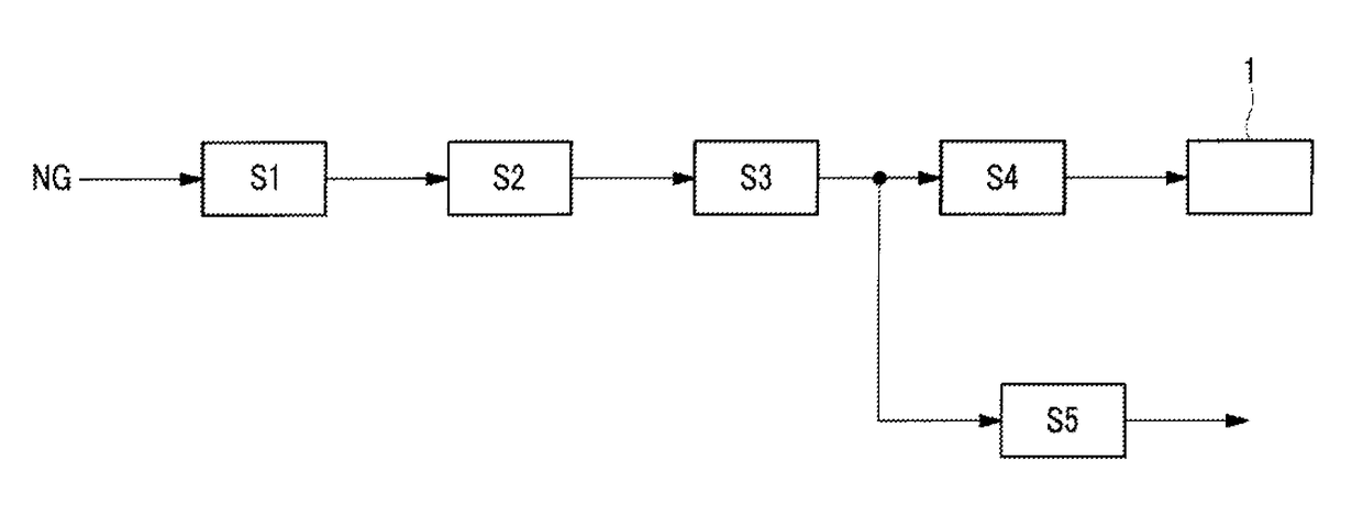
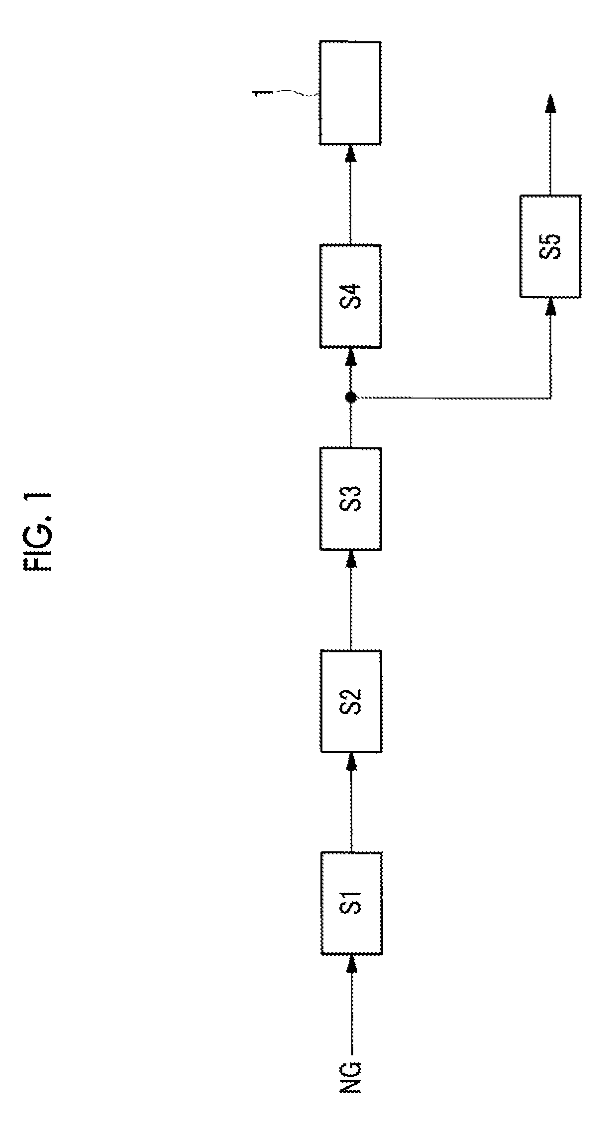
[0029]A methanol manufacturing process in a methanol plant according to a first embodiment of the present invention is shown in FIG. 1.

[0030]First, a feed stock gas (for example, natural gas) is input to a methanol manufacturing plant (a feed stock gas input process S1). Substances (for example, sulfur or the like) which are unnecessary in a reforming process S2 (described later), of the feed stock gas input in the feed stock gas input process S1, are removed by a desulfurization device (not shown). A feed stock gas with the unnecessary substance removed in the desulfurization device is input to a reforming device called a reformer (not shown).

[0031]The feed stock gas input to the reformer is mainly methane and is supplied along with water vapor and heated by a combustion exhaust gas of fuel (for example, natural gas), thereby performing a reforming reaction mainly like the following formula, whereby carbon monoxide and hydrogen are generated (the reforming process S2).

CH4+H2O→CO+3H...

second embodiment

[0051]Next, a second embodiment of the present invention will be described by using FIG. 4.

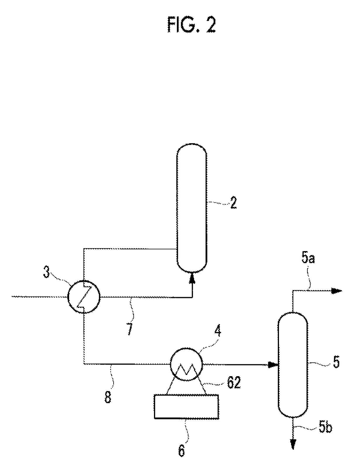
[0052]This embodiment is configured such that the heat exchanger 4 shown in the first embodiment is provided in the distillation process S4 of a methanol plant having the MTG synthesis process S5. Therefore, the same configurations as those in the first embodiment are the same reference numerals and description thereof is omitted.

[0053]In a case where a methanol plant (a gasoline synthesis plant) has the MTG synthesis process S5, a place which does not need the methanol distillation process S4 exists. As shown in FIG. 4, a pipe 22 through which a mixed gas flows is connected to a distillation column reboiler 20a. A heat source for distilling the mixed gas is supplied to a distillation column (not shown) by each of the distillation column reboilers 20a to 20d. For example, the distillation column reboilers 20a, 20b, 20c, and 20d are provided in the pipe 22. Pipes 22a, 22b, 22c, and 22d into whi...


PUM

PropertyMeasurementUnit
temperatureaaaaaaaaaa

Abstract

Provided is a methanol plant that can obtain fresh water from sea water by using, in a seawater desalination device, the exhaust heat discharged in a step for producing methanol from natural gas. The methanol plant is provided with: a heat exchanger (4) that recovers into a thermal medium (for example, seawater) the exhaust heat discharged from a step for producing methanol from a feed stock (for example, natural gas); and a seawater desalinization device (6) that obtains freshwater from seawater using the exhaust heat recovered by means of the thermal medium.

Description

TECHNICAL FIELD[0001]The present invention relates to methanol plant for producing methanol which is a synthesis gas from natural gas, and a plant for synthesizing gasoline with methanol as a feed stock.BACKGROUND ART[0002]In a methanol plant, a synthesis gas (for example, methanol) is produced from a feed stock (for example, natural gas). In a case of synthesizing methanol from natural gas, in general, a reformed gas which includes hydrogen and carbon monoxide is produced by steam-reforming natural gas, and methanol is synthesized from the gas.[0003]In a case of synthesizing methanol or methanol-via gasoline from natural gas, natural gas and water (fresh water) are required as a feed stock. However, in such a methanol plant, there is a problem in that fresh water is very scarce in a desert area of the Middle East, North Africa, or the like, or an area such as the North Pole.[0004]In a case of synthesizing methanol or methanol-via gasoline from natural gas, since fresh water is requ...

Claims


Application Information

Patent Timeline
Patent Type & Authority Patents(United States)
IPC IPC(8): B01J19/00C07C29/152B01D3/00C07C31/00C07C31/02C02F1/06B01D3/14C10G3/00C07C31/04C02F1/16C07C29/00B01J19/24C07C29/151C07C29/15B01D1/26C02F1/00C02F1/02C02F1/04B01D1/00C02F103/08
CPCC07C31/04B01D1/26B01D3/007B01D3/146B01J19/24B01J19/245C02F1/06C02F1/16C07C29/152C10G3/00Y02P30/20Y02P70/34B01J2219/0004B01J2219/24C02F2103/08C10G2400/02Y02P20/124Y02A20/124Y02P20/50Y02P20/10Y02P70/10
Inventor IIJIMA, MASAKIHIRAYAMA, HARUAKI
Owner MITSUBISHI HEAVY IND ENG LTD
Why Eureka
Try Eureka