Integrated rectifier and boost converter for wireless power transmission

a technology of boost converter and wireless power transmission, which is applied in the direction of electric variable regulation, process and machine control, instruments, etc., can solve the problems of ineffective diode efficiency, forward voltage drop, and inherently inefficient conductors, and achieve low associated heat loss, increase wireless power transmission efficiency, and low power loss characteristics

Active Publication Date: 2017-10-31
ENERGOUS CORPORATION
View PDF865 Cites 163 Cited by
  • Summary
  • Abstract
  • Description
  • Claims
  • Application Information

AI Technical Summary

Benefits of technology

[0010]According to embodiments, it is an object of the present disclosure to provide an integrated rectifier designed to include a novel rectifying circuit architecture connected to a boost converter in a wireless receiver. The architecture of the integrated rectifier may be characterized by a circuit topology of low power loss characteristics and low associated heat loss for wireless power transfer systems that may handle varying power levels to increase wireless power transmission efficiency to electronic devices, at the same time that problems encountered when using discrete circuit elements may be solved integrating the rectifier in a single package in which the novel architecture may be applied.
[0015]The architecture of the integrated rectifier may be designed to be low cost, complexity, and size.

Problems solved by technology

A typical half-bridge rectifier include two diodes which are inherently inefficient conductors producing a number of well-known problems.
One problem resulting from the inefficiency of diodes is that they produce a forward voltage drop.
Apart from reducing overall efficiency of the power converter, resulting high temperatures also reduce the reliability of components.
Thus, additional design effort may be required to overcome the problems, and other factors such as the dimensions of the system, which may be affected as a result.
Moreover, difficulties arise in the implementation of the rectifying circuit due to constraints from the available mounting area and requirements for high output and efficiency, since the rectifying circuit typically uses passive devices having large external parameters.
Additionally, the rectifying circuit does not operate over a large range of frequencies since it is an external packaged active device.

Method used


Image

  • Integrated rectifier and boost converter for wireless power transmission
  • Integrated rectifier and boost converter for wireless power transmission
  • Integrated rectifier and boost converter for wireless power transmission

Examples


Embodiment Construction

[0027]The present disclosure is here described in detail with reference to embodiments illustrated in the drawings, which form a part here. Other embodiments may be used and / or other changes may be made without departing from the spirit or scope of the present disclosure. The illustrative embodiments described in the detailed description are not meant to be limiting of the subject matter presented here.

Definitions

[0028]As used here, the following terms may have the following definitions:

[0029]“Electronic device” refers to a device depending on the principles of electronics and using the manipulation of electron flow for its operation. In present disclosure, refers to a device able to communicate using one or more suitable wireless technologies.

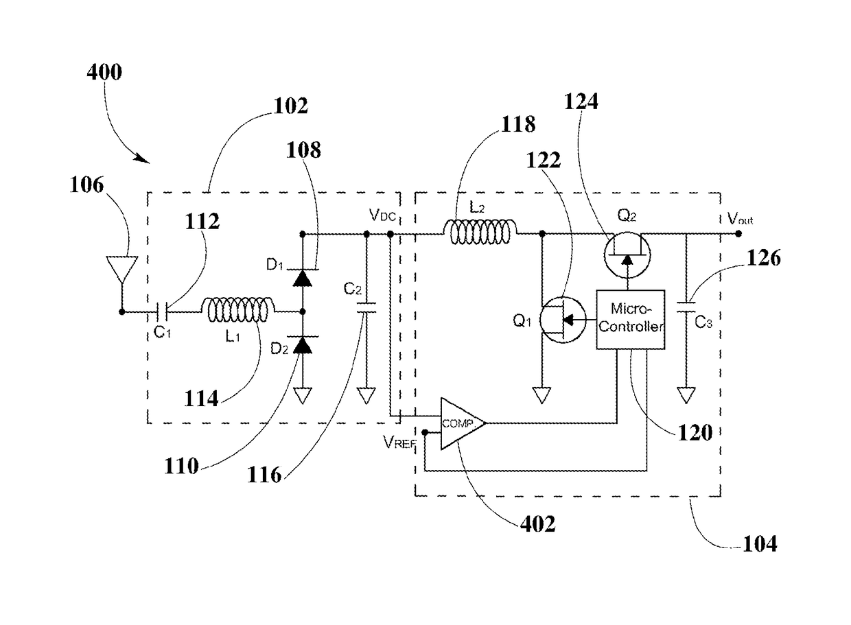
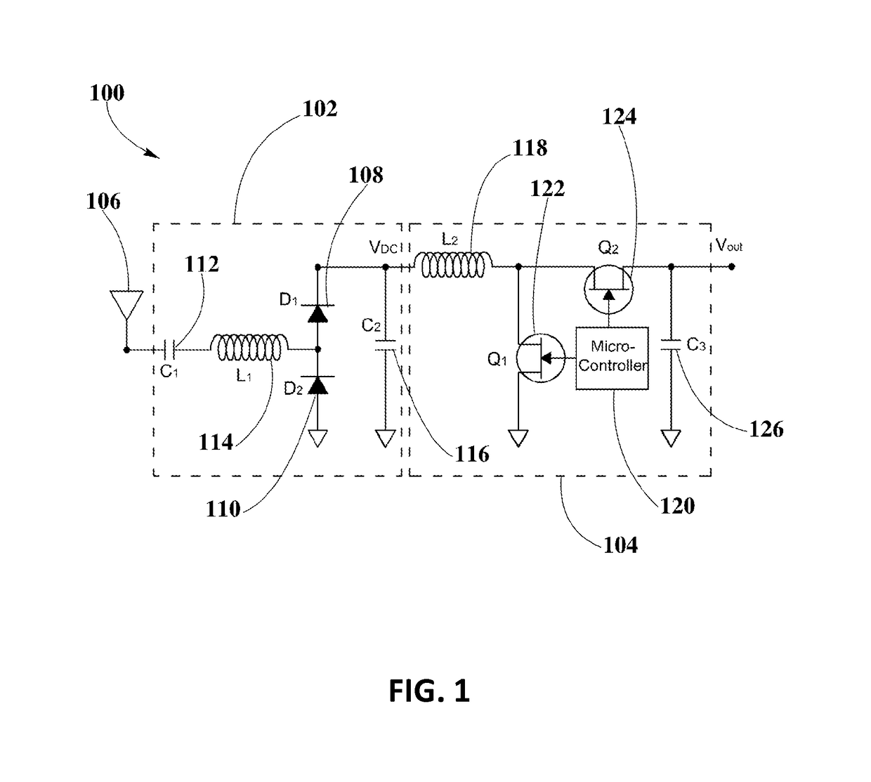
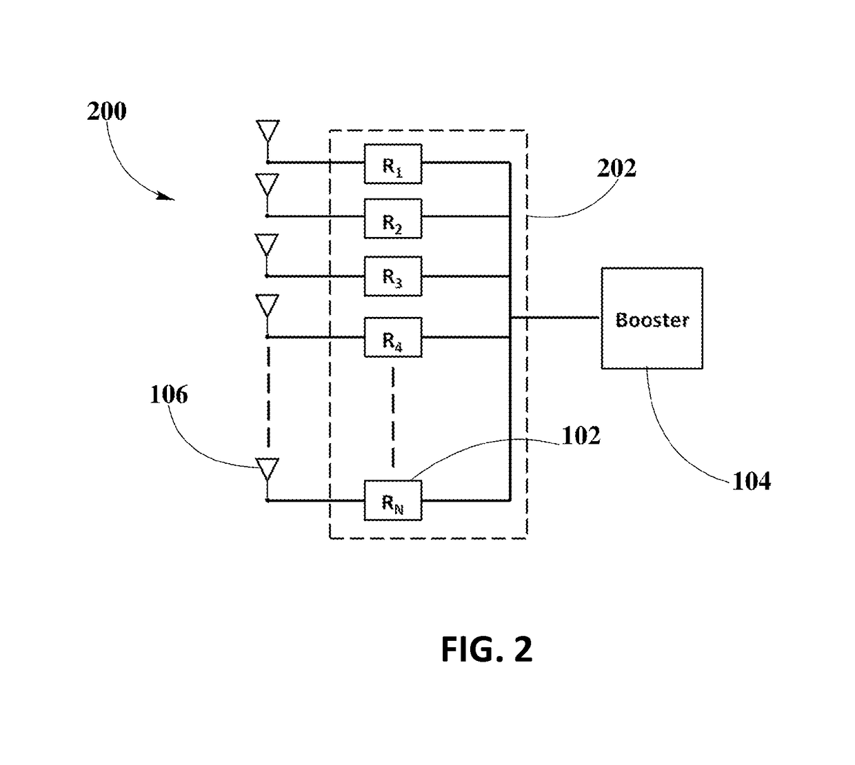
[0030]“Wireless receiver” refers to a device including at least one antenna element, at least one rectifying circuit and at least one power converter, which may utilize pockets of energy for powering, or charging a wireless device.

[0031]“Recti...


PUM


Abstract

A novel integrated rectifier and boost converter circuit architecture is disclosed. The rectifier architecture includes a plurality of identical half-bridge rectifiers connected to receiving antennas to convert wireless AC power into DC power. The integrated rectifier may be coupled in series with a charging inductor in a boost converter. The inductor may discharge upon operation of two micro-controller-driven switching transistors using predetermined threshold and timing scheme to turn on / off. The rectifier architecture may provide high power densities, improve efficiency at larger load currents, and may be enabled in an integrated circuit with eight RF signal inputs, eight half-bridge rectifiers, and eight DC outputs ganged together as single feed into the boost converter. The rectifier circuit topology may include a comparator driven by the boost controller with a proprietary algorithm which suits control for a maximum power point tracking functionality, and an external micro-controller for additional control of the boost converter.

Description

CROSS-REFERENCE TO RELATED APPLICATIONS[0001]The present disclosure is related to U.S. non-provisional patent application DWV-3DPF-010 entitled “Methodology for Pocket-forming”; DWV-3DPF-015 entitled “Method for 3 Dimensional Pocket-forming”; DWV-3DPF-027 entitled “Receivers for Wireless Power Transmission”; DWV-3DPF-029 entitled “Transmitters for Wireless Power Transmission”, invented by Michael A. Leabman; ENG-SYHW-001 entitled “Enhanced Receiver for Wireless Power Transmission”, invented by Jason Petras and Michael A. Leabman; and ENG-SYHW-003 entitled “Synchronous Rectifier Design for Wireless Power Receiver”, invented by Jason Petras and Michael A. Leabman, each of which is incorporated by reference in its entirety herein.BACKGROUND[0002]Field of the Disclosure[0003]This disclosure relates generally to wireless power transmission, and, more particularly, to integrated half-bridge rectifiers of novel design architecture, using a circuit topology of high efficiency power conversi...

Claims


Application Information

Patent Timeline
Patent Type & Authority Patents(United States)
IPC IPC(8): H02J50/20H02M7/217H02M7/06H02M3/156H02M3/158H02M1/00G05F1/67
CPCH02M3/156H02M7/06H02M7/066H02M7/217H02J50/20H02M3/1588H02M2001/007H02M2001/0022Y02B70/1466G05F1/67Y02B70/10H02J50/402H02M1/0022H02M1/007H02M7/05H02J50/80
Inventor LEABMAN, MICHAEL
Owner ENERGOUS CORPORATION
Why Eureka
Try Eureka