Separation membrane element
a technology of membrane elements and membrane elements, applied in membrane technology, membrane processes, membranes, etc., can solve the problem that existing separation membrane elements are not sufficient in separation performance, and achieve the effect of high separation efficiency, stable permeation side, and high permeation performan
- Summary
- Abstract
- Description
- Claims
- Application Information
AI Technical Summary
Benefits of technology
Problems solved by technology
Method used
Image
Examples
example 1
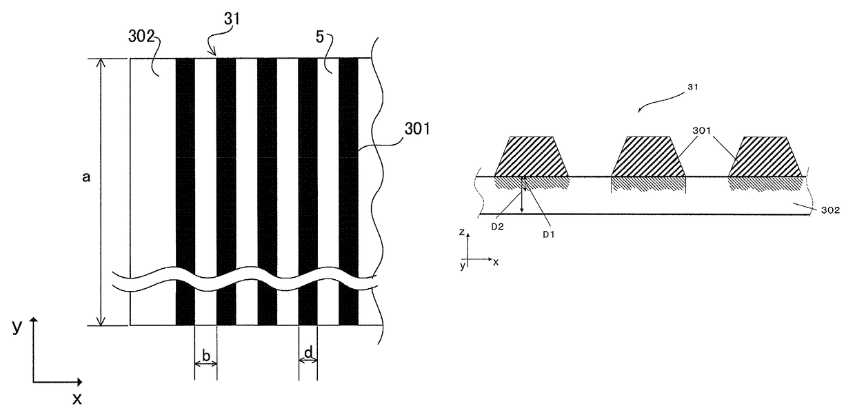
[0234]On a nonwoven fabric (polyethylene terephthalate, single fiber fineness: 1 decitex, thickness: about 0.08 mm, unit weight 1.0 g / cm2), a DMF solution of 16.0 mass % polysulfone was cast to be in a thickness of 200 μm at room temperature (25° C.), and immediately this was immersed in pure water, left therein for 5 minutes, and then immersed in hot water at 80° C. for 1 minute to obtain a porous supporting layer of a fiber-reinforced polysulfone supporting membrane having a thickness of 0.12 mm.
[0235]Subsequently, the porous supporting layer roll produced in the manner as above was unwound, 6.0 mass % m-PDA was applied onto the polysulfone surface, nitrogen was sprayed thereon through an air nozzle to remove the excessive aqueous solution from the surface of the supporting membrane, and thereafter an n-decane solution containing 0.165 mass % trimesic acid chloride at a temperature of 25° C. was applied so as to completely wet the surface to obtain a separation membrane. Thus prod...
examples 2 to 7
[0240]Separation membranes were produced in the same manner as in Example 1, except that the maximum value, the minimum value, a ratio of maximum value / minimum value and the variation coefficient of the projection heights and the tensile strength in the machine direction of the sheet having the projections fixed thereto were changed as shown in Table 1. The height variation of the permeate-side channel members and the peelability of the permeate-side channel members were evaluated, and the values shown in Table 2 were obtained. The 8-inch separation membrane element was tested in a maneuvering test to measure the fresh water production rate, the TDS removal ratio and the membrane sinking amount. Table 2 shows the obtained data.
examples 8 to 15
[0241]The maximum value, the minimum value, a ratio of maximum value / minimum value and the variation coefficient of the projection heights were changed as shown in Table 1. Also, the thickness, the air permeability, and the tensile strength and the tensile elongation in the machine direction and the cross direction of the sheet constituting the permeate-side channel member, and the tensile strength in the machine direction of the sheet having the projections fixed thereto were changed as shown in Table 1. The height variation of the permeate-side channel members and the peelability of the permeate-side channel members were evaluated, and the values shown in Table 2 were obtained.
[0242]The sheet having projections fixed thereto and the sheet with no projections were stacked on the permeate-side of the resultant leaf, and spirally wound around an ABS-made water collection tube (width; 1,020 mm, diameter; 30 mm, 40 holes×one linear line), and a film was further wound around the outer p...
PUM
| Property | Measurement | Unit |
|---|---|---|
| tensile elongation | aaaaa | aaaaa |
| tensile elongation | aaaaa | aaaaa |
| height | aaaaa | aaaaa |
Abstract
Description
Claims
Application Information
 - R&D
- Intellectual Property
- Life Sciences
- Materials
- Tech Scout
- Unparalleled Data Quality
- Higher Quality Content
- 60% Fewer Hallucinations
Browse by: Latest US Patents, China's latest patents, Technical Efficacy Thesaurus, Application Domain, Technology Topic, Popular Technical Reports.
© 2025 PatSnap. All rights reserved.Legal|Privacy policy|Modern Slavery Act Transparency Statement|Sitemap|About US| Contact US: help@patsnap.com


