Heart rate sensor and medical diagnostics wireless devices

a wireless device and heart rate sensor technology, applied in the field of heart rate sensors and medical diagnostics wireless devices, can solve the problems of not being able to provide enhanced services to mobile users over a wide area, not having readily and widely accessible cellular and cellular interconnections, and many wide bandwidth applications and services that are rapidly evolving, etc., to achieve high speed operation, improve performance, and extend coverage

Inactive Publication Date: 2017-11-07
FEHER KAMILO
View PDF344 Cites 18 Cited by
  • Summary
  • Abstract
  • Description
  • Claims
  • Application Information

AI Technical Summary

Benefits of technology

[0185]Multiuse wireless communication applications, having extended coverage, improved performance, seamless interoperability, high speed operation, enhanced capacity, multipurpose, multi functionality, multi-mode and multi standard interoperability are highly desired. The current application discloses multiuse and or multipurpose applications, devices and systems, including systems for: position determination, location finding based services and applications, remote control, wireless, wire, cabled, internet, web based communication systems, communicator devices, radio frequency identification (RFID) systems with single or plurality of devices, emergency and other alarm systems, medical patient monitor-sensor devices, medical diagnostics devices, fingerprint identification, fingerprint control, interactive communication or control of communications and control systems, communications, broadcasting, teleinformatics and telemetry systems.
[0193]To remove or minimize cables for patient monitoring systems new architectures, structures and embodiments for multi mode, multi standard, non standardized wireless, wire, cabled, infrared, multiple “cascaded” switched and combined solutions and systems are presented in this disclosure. This include cascade of cellular i.e. GSM or GSM switched to CDMA systems, with short range wireless systems—one or multiple such as Wi-Fi, Bluetooth or other. Motivation for reducing the number of cables include, the desire to eliminate the cumbersome cables connected to the patient, facilitate the surgery, and facilitate and speed up the patient recovery—enabling the patient to move, exercise and improve the quality of life of the patient during surgery, recovery and post recovery monitoring and shorten emergency time response including a remote physician, nurse or other authorized health provider—in a reverse link to control-administer certain medical—pharmaceutical items, e.g. insulin or other: also to eliminate or reduce cable caused potentially harmful currents to the patient. The term reverse link means the link (signal flow) from the physician, nurse or other authorized health provider to the patient or patients medical device; the term forward link refers to the link from the patients medical device, e.g. from the cardiac stimulation device to the physician, nurse or other authorized health provider or health monitoring system.

Problems solved by technology

Hence, many wide bandwidth applications and services that are rapidly evolving, for example, on the Internet, have not to date readily and widely accessible cellular and cellular interconnections to mobile wireless users via wireless local area networks (WLAN) and / or other wideband networks.
However, the WLAN systems only provide short range coverage, are not widely deployed, or do not provide for user mobility and hence are not generally suitable of providing enhanced services for mobile users over a wide area.

Method used


Image

  • Heart rate sensor and medical diagnostics wireless devices
  • Heart rate sensor and medical diagnostics wireless devices
  • Heart rate sensor and medical diagnostics wireless devices

Examples


Embodiment Construction

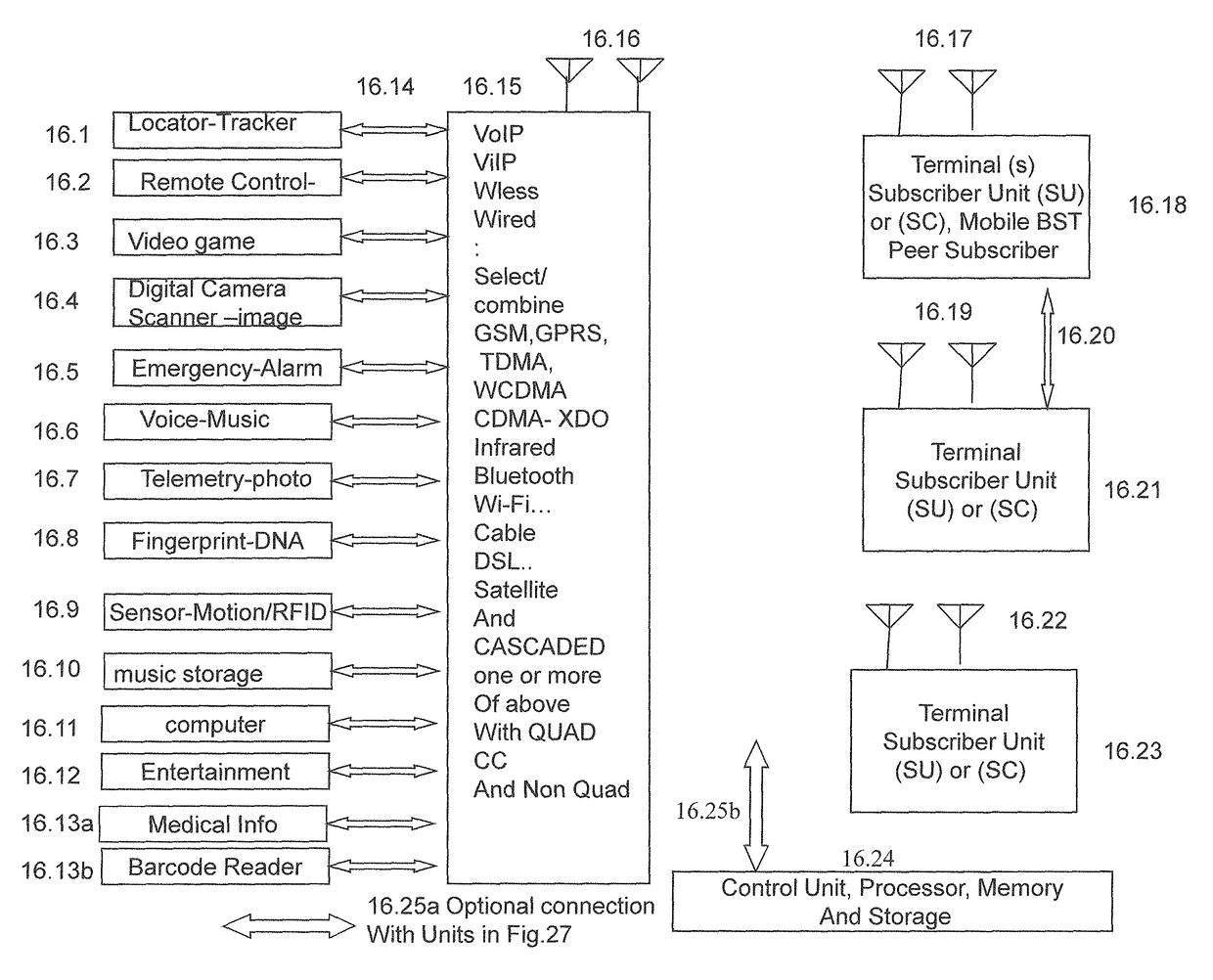
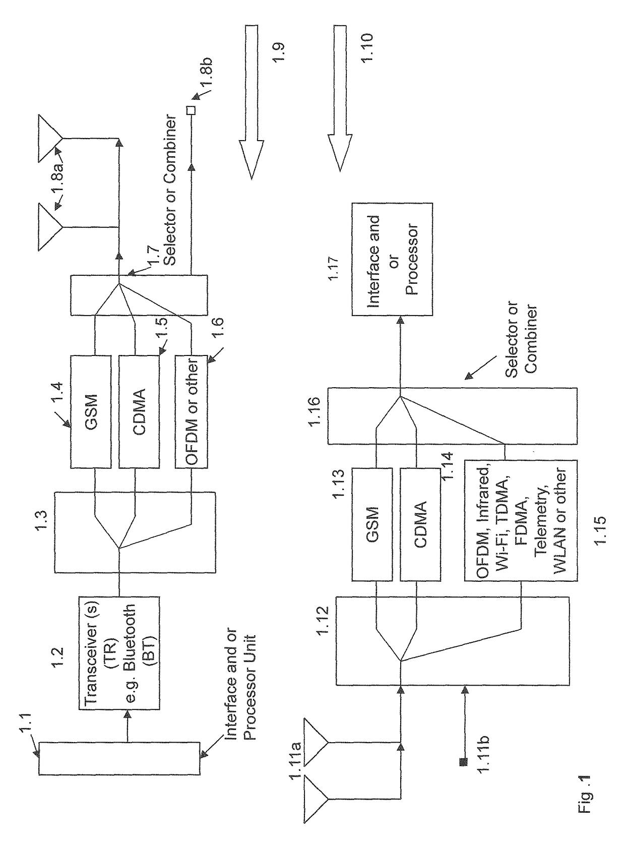
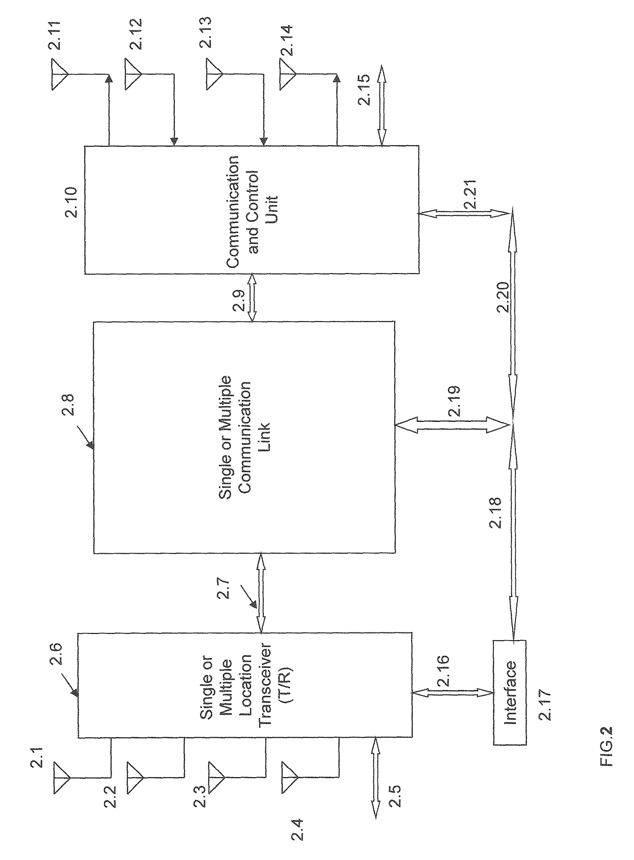
[0231]In this section, the present invention is more fully described with reference to the accompanying drawings in which preferred embodiments of the invention are shown. This invention may, however, be embodied in many different forms and should not be construed as limited to the illustrated embodiments set forth herein. Rather, these embodiments are provided so that this disclosure will be thorough and complete, and will fully convey the scope of the invention to those skilled in the art.

[0232]One or more devices (alternatively designated as units, elements, systems, terminals, devices, leads or connections) are optional in the embodiments. The elements may be interconnected and or used in various configurations. In the figures and relevant descriptions of the figures, as well as in the specifications of this disclosure, some of the units or elements are optional and are not required for certain applications, embodiments and or structures. In this document the term “signal” has t...


PUM


Abstract

A heart generated signal is provided by a heart sensor of a mobile device to an analog to digital (A / D) converter for A / D converting the sensor provided signal. The A / D converted heart signal is processed to provide heart rate. The heart rate is recorded or stored in the mobile device or is transmitted in a wireless communication system. The mobile device receives sensor provided Electro Cardiogram (ECG) signal. The ECG signal is stored or is provided to an interface unit. The mobile device has transceivers for receiving and transmitting Orthogonal Frequency Division Multiplexed (OFDM) signals and for modulating and transmitting spread spectrum baseband signals. The spread spectrum baseband signals have cross-correlated in-phase and quadrature-phase filtered baseband signals.

Description

RELATED APPLICATIONS[0001]The current application is filed as a continuation application of U.S. utility patent application Ser. No. 14 / 924,619 entitled: “Fingerprint Authenticated and Touchscreen Controlled Cascaded 3G-OFDM Mobile Systems”, filed on Oct. 27, 2015 and is scheduled to issue as U.S. Pat. No. 9,319,212 on Apr. 19, 2016 and is filed as a continuation application of U.S. utility patent application Ser. No. 14 / 025,683 entitled: “DNA, blood, heart, glucose, body temperature, skin and other medical diagnostic communications”, filed on Sep. 12, 2013 and now U.S. Pat. No. 9,173,566, issued on Nov. 3, 2015 and is filed as a continuation application of U.S. utility patent application Ser. No. 13 / 552,629, entitled: “Ship Based Cellular and Satellite Communication”, filed on Jul. 18, 2012, now U.S. Pat. No. 8,542,715 and of U.S. utility patent application Ser. No. 11 / 927,686, entitled: “Polar and quadrature modulated cellular, WiFi, WiLAN, satellite, mobile, communication and pos...

Claims


Application Information

Patent Timeline
Patent Type & Authority Patents(United States)
IPC IPC(8): H04L27/00H04B1/707H04L5/00H04W12/06H04B1/10H04B1/69H04B7/04H04M7/00A61B5/01A61B5/024A61B5/145H04J11/00H04B7/26H04L1/00H04L5/14H04L27/26G06F19/00H04W64/00H04W88/06A61B5/00H04B1/709H04L27/20H04W4/02H04W4/22H04W88/02H04W4/90
CPCH04L27/2602A61B5/0022A61B5/01A61B5/024A61B5/14532G06F19/322G06F19/3487H04B1/1036H04B1/69H04B1/707H04B1/709H04B7/04H04B7/2628H04J11/00H04L1/0003H04L5/0007H04L5/1453H04L27/2017H04L27/2071H04L27/2627H04L27/2649H04M7/006H04W4/023H04W4/025H04W4/22H04W12/06H04W64/00H04W88/06A61B5/0015H04W88/02H04B2201/70715H04B2201/70716A61B5/7228A61B5/7475A61B5/002A61B5/0077A61B5/02055A61B5/1172H04L5/0023H04L27/0008H04L27/2601A61B5/7253G16H10/60G16H15/00H04W4/90H04B7/18504Y02A90/10A61B5/349H04W12/79
Inventor FEHER, KAMILO
Owner FEHER KAMILO
Why Eureka
Try Eureka