Occlusion device and method for its manufacture

a technology of occlusion device and manufacturing method, which is applied in the field of medical device and the manufacturing, can solve the problems of increasing the risk of metal wire breaking at that location, affecting the physiological environment of surrounding tissues, and obvious structural defects, so as to reduce the amount of metal released by the occluder over the long term, facilitate epithelialization, and reduce the resistance of entering the sheath.

Active Publication Date: 2018-01-30
LIFETECH SCI (SHENZHEN) CO LTD
View PDF11 Cites 11 Cited by
  • Summary
  • Abstract
  • Description
  • Claims
  • Application Information

AI Technical Summary

Benefits of technology

[0029]Compared with the prior art, the present invention has the following merits. Since the occluder of the present invention has no permanent metal closure head, the amount of the metal released by the occluder over the long term is reduced. The long-term electrochemical corrosion in that part is eliminated. The long-term damage caused by the permanent protrusion of the closure head to the tissues of the human body can be avoided. The occluder of the present invention is more conducive to epithelialization by the host tissue. In addition, since the occluder of the present invention has a multistage braided mesh, wire accumulation incurred when the distal end of the occluder is placed back into the sheath can be well avoided. The resistance of entering the sheath can be reduced significantly so that the occluder is suitable for smaller sheaths to lower the difficulty and risk of the surgery. The occluder of the present invention is more suitable for younger patients with relatively small blood vessels.

Problems solved by technology

Although the aforementioned two occluders can occlude cardiac septal defects or blood vessels, they both have obvious structural defects.
If the closure head and the metal mesh are made of different metal materials, local galvanic corrosion will occur, and the electric field thereof will damage the physiological environment of the surround tissues and increase the risk of having broken metal wires at that location.
The large amount of metal ions released also has an adverse effect on the surrounding tissues over the long term.
Meanwhile, since the closure head sticks out permanently, it not only causes long-term damage to the tissues inside the heart but also is not conducive to epithelialization by the endothelial tissue.
However, when this occluder is placed back into the sheath, serious accumulation of metal wires will occur at the distal end.
As a result, the resistance incurred when placing the occluder back into the sheath during the surgery becomes excessively large (if a larger sheath is used, extra damage will be caused by the sheath to the vascular wall).
The risk of the surgery is increased.

Method used


Image

  • Occlusion device and method for its manufacture
  • Occlusion device and method for its manufacture
  • Occlusion device and method for its manufacture

Examples


embodiment 1

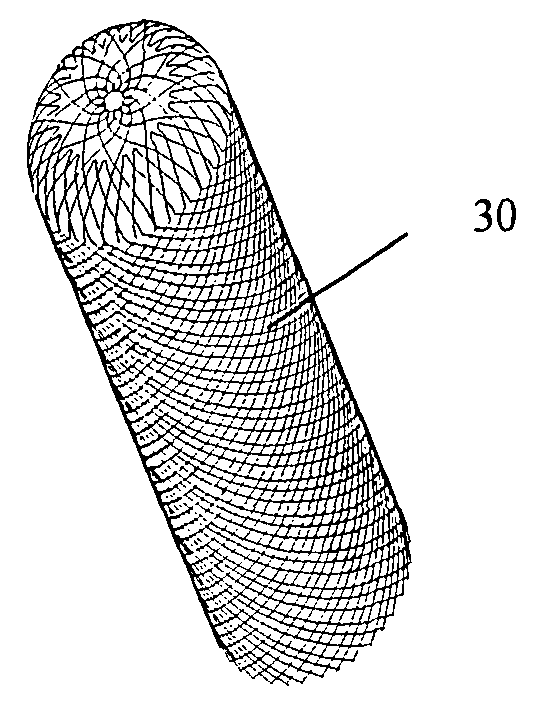
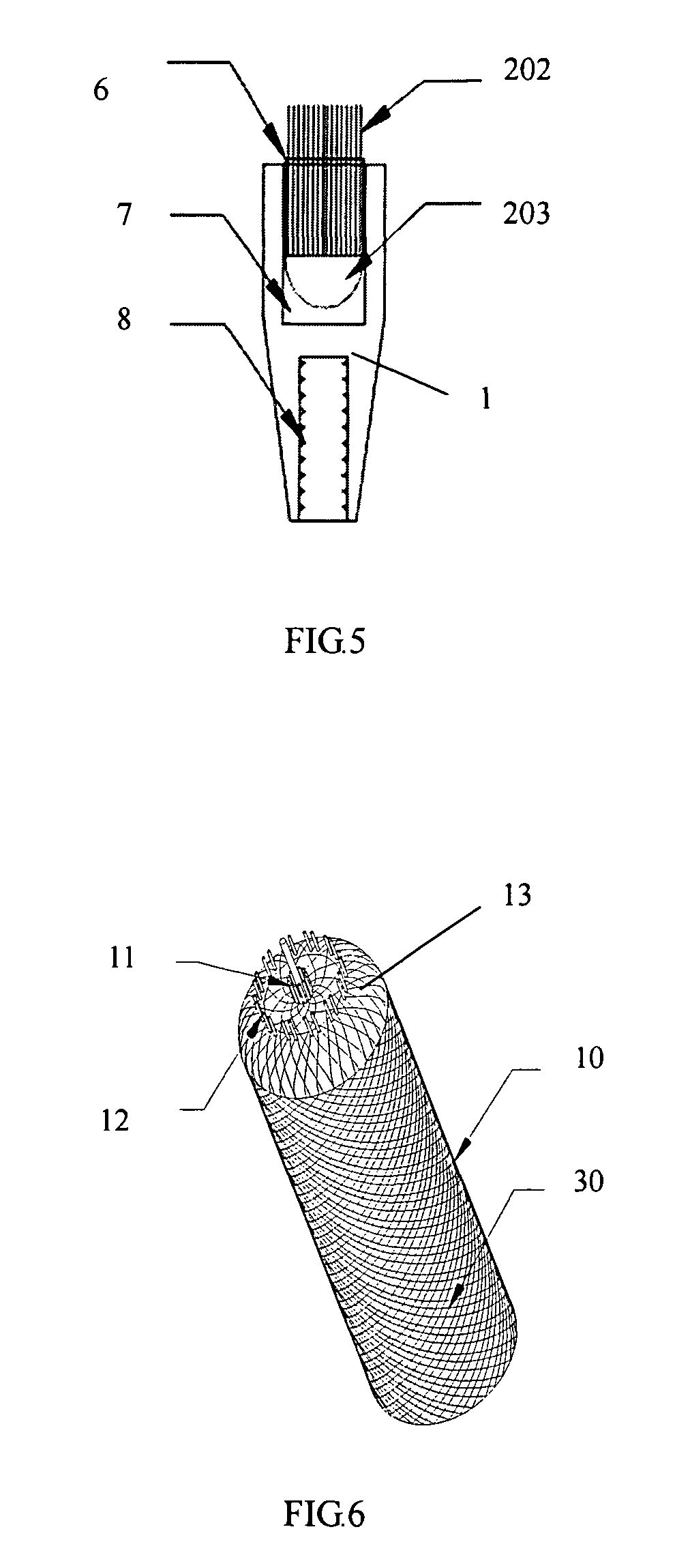
[0076]As shown in FIG. 6, nickel-titanium alloy wires are first used to braid a metal mesh tube 30 on a cylindrical metal molded rod 10. A braiding chuck 13 is provided in the head part of molded rod 10. Holes are formed on two concentric circles around the axis of molded rod 10. Twelve holes are arranged symmetrically with respect to the axis on the first circle. Twenty-four holes are arranged on the outer second circle. Twelve rays are led out from the center of the circle to the twelve holes on the inner circle and cross with the outer circle at twelve points. These twelve points and the twenty-four holes on the outer circle are uniformly distributed on the outer circle. There are two holes between two adjacent points. A two-stage braided mesh is formed in this embodiment. Therefore, it is necessary to form two circles of holes on braiding chuck 13. Similarly, a plurality of circles of holes can be formed for a multistage braided mesh, and the braiding method is also similar.

[007...

embodiment 2

[0081]The second embodiment of the present invention is modified based on the first embodiment. When placing the first-stage wires 21, one of the first-stage wires penetrates the bent parts of all the other first-stage wires on the first-stage wire hanging bars 11. This first-stage wire is hung on the corresponding first-stage wire hanging bar 11 after it forms a ring around the other first-stage wire hanging bars 11 on the same circle, followed by starting braiding of the first-stage braided mesh 221, as shown in FIG. 20. The steps thereafter are basically the same as those of the first embodiment except that the step of using suture thread 70 to connect opening 32 is omitted, because the same objective can be achieved by the second embodiment.

embodiment 3

[0082]The third embodiment is modified based on the first embodiment of the present invention. The first several steps are exactly the same as those of the first embodiment. When placing the second-stage wires 22, each second-stage wire 22 forms a small ring around one second-stage wire hanging bar 12, followed by braiding the two formed branches of each wire as shown in FIG. 21. The steps thereafter are exactly the same as those of the first embodiment. When the wires are bent into small rings, they are difficult to break during compressive deformation so that the safety of the metal mesh can be improved. The suture thread can also easily penetrate these small rings.


PUM


Abstract

An occlusion device comprises a distal end, a proximal end and an elastic braided body which is provided between the proximal end and the distal end and made of wires. The elastic braided body is composed of a multi-stage braided net, which comprises at least a first-stage braided net that is closest to the distal end and made of a plurality of first-stage wires, and a second-stage braided net which is braided by a plurality of first-stage wires and second-stage wires all together. The minimum cross-section area of the first-stage braided net after being compressed toward the direction perpendicular to an axis of the elastic braided body is less than the minimum cross-section area of any other-stage braided net after being compressed toward the axis. A method for manufacturing the occlusion device is also provided.

Description

TECHNICAL FIELD[0001]The present invention relates to a medical device and the manufacturing, method therefore. In particular, the present invention relates to an interventional treatment device for occluding defects in heart or blood vessels and the manufacturing method thereof.BACKGROUND[0002]In company with the continuous development of interventional materials and devices as well as interventional cardiology, minimally invasive treatment using an interventional occluder via catheter has become an important method for treating ventricular septal defect (VSD), atrial septal defect (ASD), patent ductus arteriosus (PDA), patent foramen ovale (PFO) and other congenital heart diseases. In addition, it is a widely accepted treatment method for carrying out endovascular closure using an intervention means.[0003]For example, Chinese Patent No. 97194488.1 discloses a heart occluder. As shown in FIGS. 1 and 2, this heart occluder comprises bolt head 1, metal mesh 2, flow-occluding membrane...

Claims


Application Information

Patent Timeline
Patent Type & Authority Patents(United States)
IPC IPC(8): A61B17/12D04C1/06A61B17/00
CPCA61B17/12109A61B17/0057A61B17/12172D04C1/06D10B2509/06A61B2017/00526A61B2017/00592A61B2017/00606A61B2017/00867A61B2017/00004
Inventor LIU, XIANGDONGZENG, WEIJUN
Owner LIFETECH SCI (SHENZHEN) CO LTD
Why Eureka
Try Eureka