High frequency phase reference standard signal

Active Publication Date: 2018-02-20
FOCUSMW IP
View PDF3 Cites 0 Cited by
  • Summary
  • Abstract
  • Description
  • Claims
  • Application Information

AI Technical Summary

Benefits of technology

[0007]As mentioned above, the non-linear circuit may be in the form of an amplifier circuit. Such an amplifier circuit may provide bandwidth advantages. Such an amplifier circuit may be readily adapted for a particular purpose. An amplifier may produce stronger harmonic content under high drive due to the significant non-linearities present. An amplifier may be less sensitive to high drive power as compared to, say other non-linear devices such as non-linear transmission lines. Amplifier circuits capable of operating at the very high frequencies required are readily available. As an amplifier has gain, attenuators can be used at the input and output of the amplifier to improve the sensitivity to the impedance environment surrounding the phase reference, which is a known problem with other phase reference technologies.
[0009]In accordance with the method of the invention, at least two of the harmonic components are at the tenth or lower harmonic frequencies. As mentioned above, the signal strength of such low-order harmonic components may be relatively high, thus enabling the provision of a pre-characterised high frequency multi-tone signal from the amplifier circuit with high signal to noise ratio. The number of harmonic components generated by the amplifier circuit may be limited but may nevertheless provide a sufficient number of harmonic components with sufficient energy focussed on the frequencies of interest, making noise less of an issue. This may lead to increased accuracy in the phase measurements. The use of an amplifier circuit, based on standard transistor technology, may lessen or remove the need for further development in pulse / comb generators whenever higher frequency VNAs become available, because such amplifiers and transistors are already available at frequencies greater than 100 GHz. Coping with such higher frequency VNA capability should therefore simply be a matter of scaling the amplifier circuit of the present invention as required.
[0027]ascertaining at least one of (a) absolute phase information from the signals so measured and (b) a time domain representation relating to the signals so measured. This can be achieved by means of using a pre-characterised high frequency multi-tone signal and information concerning the phase relation of the harmonic frequency components of said pre-characterised high frequency multi-tone signal, both being provided by means of any aspect of the present invention described or claimed herein. The phase reference standard provided by the present invention for use in this measurement method preferably provides a stable, harmonically rich signal, which is pre-characterized with known harmonic phase relationships over the entire measurement bandwidth.
[0028]The high frequency signal applied to the device under test may be phase-locked with the first signal supplied to the amplifier circuit. The first signal supplied to the amplifier circuit may be otherwise phase-locked with the measurement apparatus. The measurement apparatus may have its own one or more internal signal generators and such one or more signal generators may be used to provide both the first signal to the amplifier circuit and the trigger signal for the measurement apparatus. The measurement apparatus may be triggered by the same signal as fed to or supplied by the amplifier circuit. Unlike alternative approaches which typically use two reference standards, one to trigger the measurement apparatus and one to correct for absolute phase, the present embodiments of the present invention may allow for simultaneous triggering and correction.

Problems solved by technology

As an amplifier has gain, attenuators can be used at the input and output of the amplifier to improve the sensitivity to the impedance environment surrounding the phase reference, which is a known problem with other phase reference technologies.

Method used


Image

  • High frequency phase reference standard signal
  • High frequency phase reference standard signal
  • High frequency phase reference standard signal

Examples


first embodiment

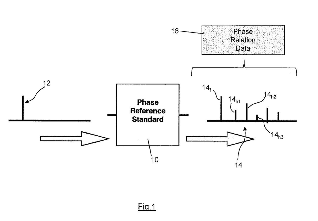
[0042]FIG. 1 shows schematically the present invention. A phase reference standard system is provided, which comprises an amplifier circuit 10. The phase reference standard system produces a reference standard, at a given frequency, which can then be used in any application that requires a pre-characterised multi-tone high frequency signal with known phase relation information. The reference standard has particular application in systems that operate at the GHz frequency range but may have application at lower frequencies, for example, down to 100 MHz level (which in most electronics application would still be termed as high frequency). The reference standard may for example enable the absolute phase information in respect of measurements made using a VNA to be determined The reference standard may be used in calibration procedures. The reference standard may be used to verify calibration procedures effected by other independent means.

[0043]The amplifier circuit 10 of the phase refe...

second embodiment

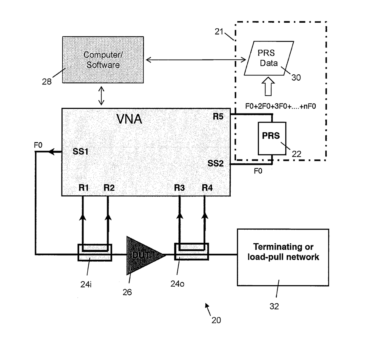
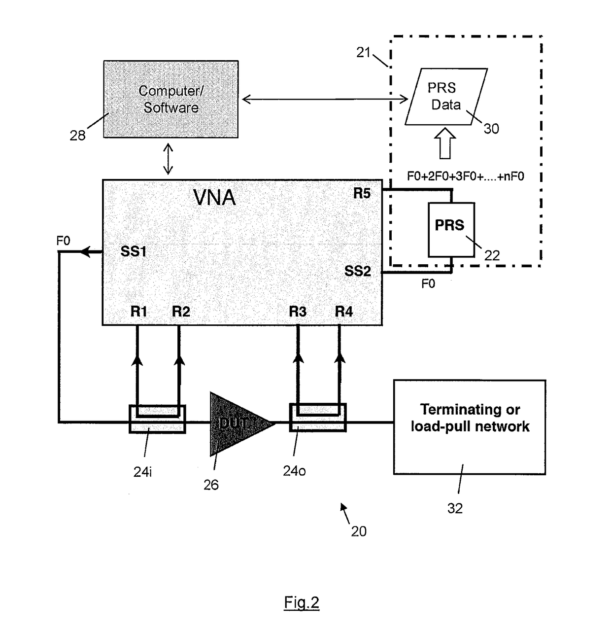
[0045]the invention is shown in FIG. 2, which illustrates schematically a measurement system 20 including a phase reference standard system 21. A Vector Network Analyser (VNA), such as a ZVA-67 available from Rohde and Schwarz, is connected to measure the response characteristics of a DUT (device under test) 26. A port of the DUT 26 is connected to a first signal source (SS1)—a simple mono-tone signal at a fundamental frequency F0. A first directional coupler 24i is used to sample a portion of the forward and reflected travelling waves at the input of the DUT 26. A second directional coupler 24o is used to sample a portion of the forward and reflected travelling waves at the output of the DUT 26. The forward and reflected travelling waves at both input and output of the DUT 26 (four travelling waves in total) are then measured by the receivers of the VNA (receivers R1-R4). The phase reference standard system 21 includes a reference signal generator 22, which is connected to a 5th me...

fourth embodiment

[0055]FIG. 4 shows a phase reference standard system 60 according to a The phase reference standard system 60 comprises first and second amplifier circuits 62, 64 arranged in parallel. A single input signal 61 at the fundamental frequency is split by means of a signal splitter 63 into two substantially identical sub-signals of the same magnitude (but possibly different phase), one sub-signal being fed to the first amplifier circuit 62 and the other sub-signal being fed to the second amplifier circuit 64. The first amplifier circuit 62 is a class A amplifier, whereas the second amplifier circuit 64 is a class B amplifier. The first class A amplifier circuit 62 when suitably overdriven produces strong odd harmonic content due to the symmetric clipping against the DC boundaries of the device, but relatively weak even harmonics (see the schematic frequency spectrum 66 shown in FIG. 4). The second class B amplifier circuit 64 when suitably biased produces strong even harmonic content du...


PUM

PropertyMeasurementUnit
frequenciesaaaaaaaaaa

Abstract

A pre-characterised high frequency signal (14) is provided by means of a non-linear circuit, for example an amplifier circuit (10), fed with a first signal (12) with a component at a first, fundamental, frequency (FO). The amplifier circuit generates an output signal comprising harmonic components (14h1, 14h2, 14h3) having stable and predetermined phase relation relative to each other. Information concerning the phase relation of the harmonic frequency components is provided, for example by means of a data file (16). At least two of the harmonic components are at the tenth or lower harmonic frequencies. The signal strength of such low-order harmonic components may be relative high, thus enabling the provision of a pre-characterised high frequency multi-tone signal from the amplifier circuit with high signal to noise ratio.

Description

BACKGROUND OF THE INVENTION[0001]The present invention concerns the provision of a pre-characterised high frequency signal, for example for use as a phase reference standard. More particularly, but not exclusively, this invention concerns a method of providing a pre-characterised high frequency signal and a phase reference standard generating apparatus. The invention also concerns a calibration verification method, a method of measuring the response of an electronic device to a high frequency input signal and a method of producing a data file for a phase reference standard.[0002]The provision of a pre-characterised high frequency signal for use as a phase reference standard facilitates, in the context of a high frequency measurement system, the transfer of absolute phase information to a time domain measurement system. This in turn assists with the analysing, and characterising, of the large signal behaviour of a high frequency device, commonly referred to in the art as a device und...

Claims


Application Information

Patent Timeline
Patent Type & Authority Patents(United States)
IPC IPC(8): G01N27/416H04L27/00G01R27/28G01R35/00G01R27/32G01R31/28
CPCG01R27/28G01R35/007G01R31/2841G01R27/32
Inventor BENEDIKT, JOHANNESWILLIAMS, TUDOR VYVYAN
Owner FOCUSMW IP
Why Eureka
Try Eureka