Processes for purifying acetic and hydrating anhydride

a technology of acetic acid and hydrating anhydride, which is applied in the preparation of carboxylic compounds, carbon monoxide reaction carboxylic preparations, organic chemistry, etc., can solve the problems of increasing the cost of the process, reducing the and reducing so as to achieve greater production rate of acetic anhydride and reduce the concentration of acetic anhydrid

Active Publication Date: 2018-03-06
CELANESE INT CORP
View PDF50 Cites 5 Cited by
  • Summary
  • Abstract
  • Description
  • Claims
  • Application Information

AI Technical Summary

Benefits of technology

[0019]In another embodiment, there is provided a process for purifying acetic acid comprising carbonylating, in a reactor, at least one member selected from the group consisting of methanol, dimethyl ether, and methyl acetate in a reaction medium comprising water at a concentration from 0.1 to 14 wt. %, a rhodium catalyst, methyl iodide, and an iodide salt, separating the reaction medium to form a liquid recycle stream and a vapor product stream, distilling at least a portion of the vapor product stream in a first column to obtain a side stream comprising acetic acid at a concentration greater than 90 wt. %, water at a concentration from 1 to 3 wt. %, one or more C1-C14 alkyl iodides in a total concentration of no more than 6 wt. % and methyl acetate at a concentration of no more than 6 wt. %, distilling the side stream in a second column to obtain a product stream comprising acetic acid, water at a concentration of no more than 0.2 wt. % and acetic anhydride at a concentration of no more than 600 wppm, e.g., from 10 to 600 wppm, and contacting the product stream with a cation exchange resin to form a purified acetic acid product comprising no more than 50 wppm acetic anhydride. In one embodiment, the production rate of acetic anhydride is greater in the second column than the reactor. The side stream is substantially free of acetic anhydride, e.g., the acetic anhydride concentrations are below detectable limits. The side stream may also comprise hydrogen iodide at a concentration of no more than 300 wppm. The purified acetic acid product may comprise water at a concentration of no more than 0.2 wt. % and acetic anhydride at a concentration of no more than 10 wppm. In one embodiment, the water concentration in a lower portion of the second column is maintained to be less than the water concentration of the side stream. The acetic anhydride concentration of the purified acetic acid product is less than the acetic anhydride concentration of the product stream. The cation exchange resin may reduce the acetic anhydride concentration of the product stream by at least 60%. In further embodiments, the process comprises contacting the purified acetic acid product with a metal-exchanged ion exchange resin having acid cation exchange sites to reduce the iodide concentration of the purified acetic acid product to no more than 100 wppb.

Problems solved by technology
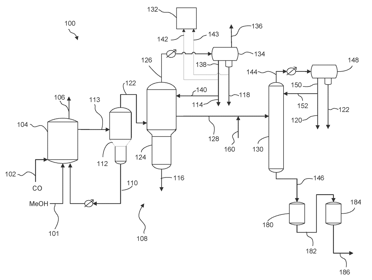
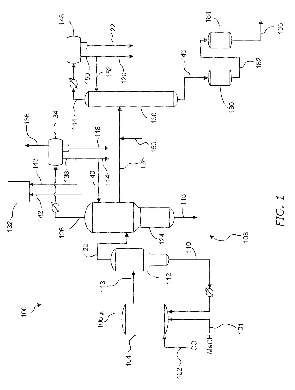
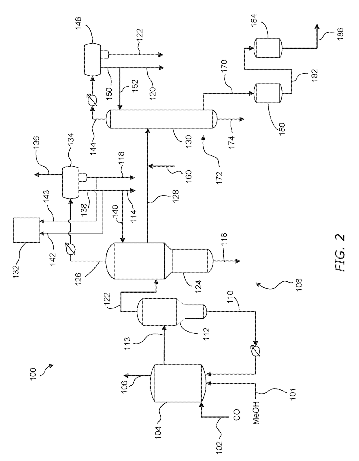
However, the additional treatment of the purified acetic acid adds cost to the process, and distillation of the treated acetic acid product can result in additional impurities being formed.
While it is possible to obtain acetic acid of relatively high purity, the acetic acid product formed by the low-water carbonylation process and purification treatment described above frequently remains somewhat deficient with respect to the permanganate time due to the presence of small proportions of residual impurities.
Because a sufficient permanganate time is an important commercial test, which the acid product may be required to meet to be suitable for many uses, the presence of impurities that decrease permanganate time is objectionable.
Moreover, it has not been economically or commercially feasible to remove minute quantities of these impurities from the acetic acid by distillation because some of the impurities have boiling points close to that of the acetic acid product or halogen-containing catalyst promoters, such as methyl iodide.
Exchange resin compositions that have little or no metal-functionality do not efficiently remove iodides and, as such, are not conventionally used to do so.

Method used


Image

  • Processes for purifying acetic and hydrating anhydride
  • Processes for purifying acetic and hydrating anhydride
  • Processes for purifying acetic and hydrating anhydride

Examples


example 1

[0131]A stream comprising acetic acid, less than 2 wt. % water, and acetic anhydride that varied from 123 to 510 ppm was fed to a column filled with Ag functionalized sulfonic resin at 8 bed volume per hour flow rate. The temperature of the resin was controlled at 75° C. The acetic anhydride concentration in the inlet and outlet of the resin column were measured by a gas chromatograph (GC) equipped with a flame ionization detector. A capillary column with dimethylpolysiloxane stationary phase was used to achieve separation in the GC analysis. Results for experiments 1-3 are shown in Table 4.

[0132]

TABLE 4Flow Through Experiments Performed at 75° C.Experiment No.Inlet Conc., ppmOutlet Conc., ppm112322235235101

example 2

[0133]Experiments 4-6 were performed with the same procedures and setup as Example 1 except the initial acetic anhydride concentration varied from 171 to 574 ppm and the resin column temperature that was controlled at 25° C. Results are shown in Table 5.

[0134]

TABLE 5Flow Through Experiments Performed at 25° C.Experiment No.Inlet Conc., ppmOutlet Conc., ppm417115333165742


PUM

PropertyMeasurementUnit
pressureaaaaaaaaaa
atmospheric pressureaaaaaaaaaa
temperatureaaaaaaaaaa

Abstract

Processes for purifying acetic acid by distilling a process in a column in which acetic anhydride is formed in the lower portion of the column. The product stream withdrawn from the column comprises acetic acid, water at a concentration of no more than 0.2 wt. %, and acetic anhydride at a concentration of no more than 600 wppm. The process further comprises hydrating the acetic anhydride in the product stream to form a purified acetic acid product comprising acetic anhydride at a concentration of no more than 50 wppm.

Description

CROSS-REFERENCES TO RELATED APPLICATIONS[0001]This patent application claims the priority of U.S. Application No. 62 / 255,060, filed Nov. 13, 2015, the disclosure of which is incorporated herein by reference in its entirety.FIELD OF THE INVENTION[0002]This invention relates to processes for producing acetic acid and, in particular, to improved processes for hydrating acetic anhydride in a product stream to form a purified acetic acid product comprising acetic anhydride at a concentration of no more than 50 wppm.BACKGROUND OF THE INVENTION[0003]Among currently employed processes for synthesizing acetic acid, one of the most useful commercially is the catalyzed carbonylation of methanol with carbon monoxide as taught in U.S. Pat. No. 3,769,329, incorporated herein by reference in its entirety. The carbonylation catalyst contains rhodium, either dissolved or otherwise dispersed in a liquid reaction medium or supported on an inert solid, along with a halogen-containing catalyst promoter ...

Claims


Application Information

Patent Timeline
Patent Type & Authority Patents(United States)
IPC IPC(8): C07C51/12C07C51/087C07C51/44C07C51/56C07C51/47
CPCC07C51/44C07C51/087C07C51/12C07C51/47C07C51/56C07C53/08C07C53/12C07C51/487C07C51/573
Inventor SHAVER, RONALD D.LIU, YAW-HWASCATES, MARK O.
Owner CELANESE INT CORP
Why Eureka
Try Eureka