Transmit/receive beamforming signal generation

a beamforming signal and beam technology, applied in the field of transmit/receive beamforming signal generation, can solve the problems of substantial system cost relative cost of rf circuit, and achieve the effects of enhancing the effective power of transmitted waveform, reducing signal loading, and reducing distortion

Active Publication Date: 2018-05-01
TEXAS INSTR INC
View PDF4 Cites 19 Cited by
  • Summary
  • Abstract
  • Description
  • Claims
  • Application Information

AI Technical Summary

Benefits of technology

[0002]In described examples, a low power transmit and / or receive antenna array system is arranged for enhancing effective power of a transmitted waveform. In at least one embodiment, trigonometric weighted vector modulation techniques for beam-focusing transmitter and phase-based waveform reconstruction are described. The techniques for trigonometric weighted vector modulation include (for example) baseband scalar weighting and quadrature-phased signals at LO (local oscillator) and RF frequencies. Multi-band operation of the transmit and receive arrays are performed in accordance with different sidebands at two or more LO frequencies combined in response to quadrature signals generated by moderate tuning range voltage-controlled oscillators (VCOs) such that, for example, a moderate tuning range VCO can be used in generating signals for a relatively wide range of operating frequencies. The local oscillator (LO) frequencies are generated coherently using reconfigurable frequency divider and multipliers. The described embodiment provides minimum signal loading at baseband frequencies, provides low distortion due to the current mode operation and sideband combination using up- and / or down-converter mixers, and permits lower power and area consumption for transmit / receive arrays.

Problems solved by technology

Each of the transmitter elements is driven by a relatively complex RF circuit such that the relative cost of the RF circuits is a substantial portion of a system cost.

Method used


Image

  • Transmit/receive beamforming signal generation
  • Transmit/receive beamforming signal generation
  • Transmit/receive beamforming signal generation

Examples


first embodiment

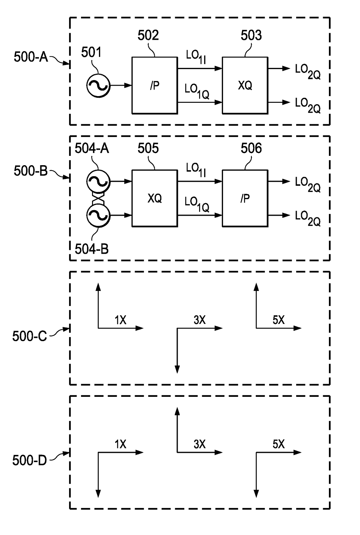
[0081](A) A first embodiment includes single sideband up-conversion mixers using LO1 signals (e.g., only), where the quantities P and Q are mutually exchanged (e.g., swapped):

RF=LOQ=>LO=1 / QRF  (Eq. 10)

[0082]Accordingly, when Q=3 and the RF center frequency is 35 GHz, the VCO frequency becomes 12.67 GHz, which is a sub-harmonic of the RF carrier frequency, such that the architecture is (e.g., mathematically) immune to frequency deviations from high PA output power via various coupling mechanisms.

second embodiment

[0083](B) A second embodiment includes single-sideband up-conversion mixers using LO2 signals (e.g., only), where the quantities P and Q are mutually exchanged (e.g., swapped):

RF=LOP / Q=>LO=Q / PRF  (Eq. 11)

[0084]Accordingly, when P=6, Q=3 and the RF center frequency is 35 GHz, the VCO frequency becomes 17.5 GHz, which is a sub-harmonic of the RF carrier frequency, such that the architecture is (e.g., mathematically) immune to frequency deviations from high PA output power via various coupling mechanisms.

third embodiment

[0085](C) A third embodiment includes single-sideband up-conversion mixers using a combination of LO1 and LO2 in additive manner:

[0086]RF=LO1+LO2=LO⁢Q⁡(P+1)P⁢⁢=>⁢⁢LO=PQ⁡(P+1)⁢RF(Eq.⁢12)

[0087]Accordingly, when P=2, Q=3 and the RF center frequency is 35 GHz, the VCO frequency becomes 7.8 GHz, which is a sub-harmonic of the RF carrier frequency, such that the architecture is (e.g., mathematically) immune to frequency deviations from high PA output power via various coupling mechanisms. Note that Q=1 leads to a simple case of sliding IF architecture (where the ratio of the LO1 / LO2 determines a division ratio in quadrature over the frequencies used in single sideband communications)


PUM


Abstract

Transmit and/or receive beamforming signal generation includes a voltage-controlled oscillator (VCO) for generating a lower or higher master frequency output signal in accordance with a selection of a lower or higher frequency carrier frequency. A local oscillator generates local oscillator signals in quadrature in response to the maser frequency output signal. One or more mixer stages generate sidebands in response to a received information signal and the local oscillator signals in quadrature. The one or more mixer stages generate an output information signal in response to high-side injection of lower sidebands of the developed sidebands when the lower frequency carrier frequency is selected, and generate the output information signal in response to low-side injection of higher sidebands of the developed sidebands when the higher frequency carrier frequency is selected. Multi-band operation of transmit and receive arrays can be performed.

Description

BACKGROUND OF THE INVENTION[0001]Next-generation communication systems include multiple-input, multiple-output (MIMO) transceivers to accommodate high data throughput in wireless transmission systems. For example, transmitters in MIMO systems are often arranged as an array of transmitter elements, where each transmitter element is coupled to respective antenna, and where individual antennas are often physically separated from an adjacent antenna by a fraction of the wavelength (e.g., a half wavelength) at a selected radio frequency (RF). Each of the transmitter elements in the array can be phase shifted with respect to adjacent transmitter elements (e.g., contiguous transmitter elements arranged in a row or column). The phase shifting of adjacent transmitter elements generates a higher effective output power based on constructive addition of electromagnetic waves in space (e.g., as compared to the sum of the average power out of each of the individual transmitter elements). Each of ...

Claims


Application Information

Patent Timeline
Patent Type & Authority Patents(United States)
IPC IPC(8): H04L1/00G06F7/487G06F7/496H03M13/00H03M13/41
CPCH04L1/0054H03M13/41H03M13/658H03M13/6597G06F7/4876G06F7/496H04B1/0042H04B7/0617H04B7/0634H04B7/086H03D7/1441H03D7/1458H03D7/165H03D2200/0023H03D2200/0082H03L7/00
Inventor CHAKRABORTY, SUDIPTO
Owner TEXAS INSTR INC
Why Eureka
Try Eureka