
Method of plasma-assisted cyclic deposition using ramp-down flow of reactant gas

a technology of reactant gas and plasma, which is applied in the direction of chemical vapor deposition coating, electric discharge tube, coating, etc., can solve the problems of unsatisfactory chemical resistance and quality of film, and achieve the effect of reducing the hydrogen content of the dielectric film, good reactivity, and efficient hydrogen cleaning

Active Publication Date: 2018-05-29
ASM IP HLDG BV
View PDF3 Cites 324 Cited by
  • Summary
  • Abstract
  • Description
  • Claims
  • Application Information

AI Technical Summary

Benefits of technology

This patent aims to describe the technical effects of an invention that has specific objectives and advantages. The invention may be implemented in a way that optimizes certain advantages without necessarily meeting all other objectives. The patent provides a summary of the invention's goals and how it can be achieved.

Problems solved by technology

However, when depositing a dielectric film such as silicon / metal nitride or oxide films by cyclic plasma-assisted deposition, where nitration or oxidation reaction is conducted in an atmosphere with plasma using a reactant such as H2 or O2, the quality of film in terms of, for example, chemical resistance is sometimes unsatisfactory.

Method used


Image

  • Method of plasma-assisted cyclic deposition using ramp-down flow of reactant gas
  • Method of plasma-assisted cyclic deposition using ramp-down flow of reactant gas
  • Method of plasma-assisted cyclic deposition using ramp-down flow of reactant gas

Examples


examples 1 and 2

, and Comparative Examples 1 and 2

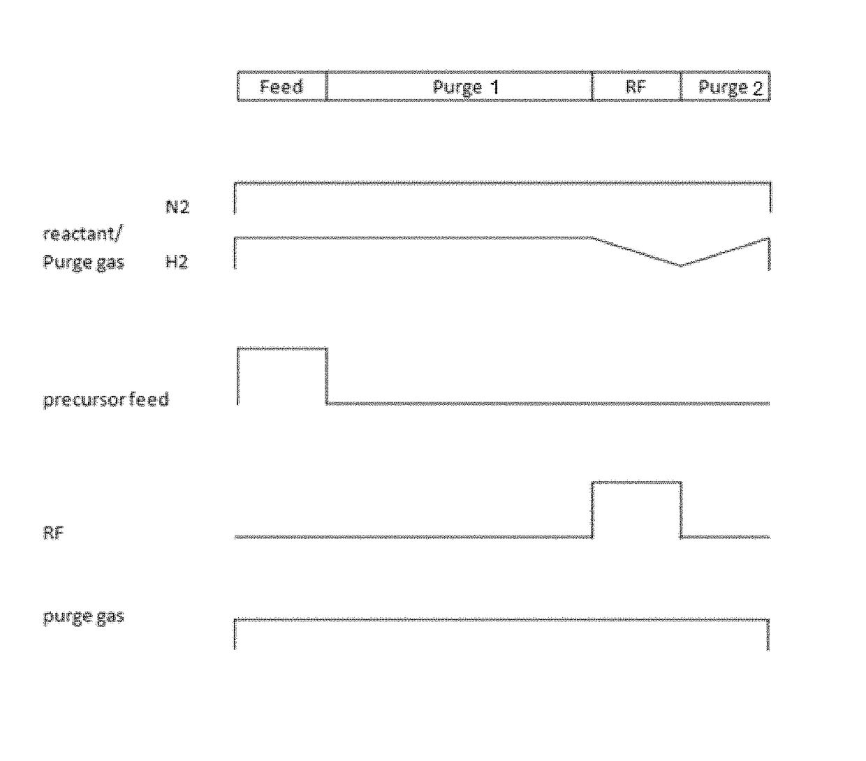
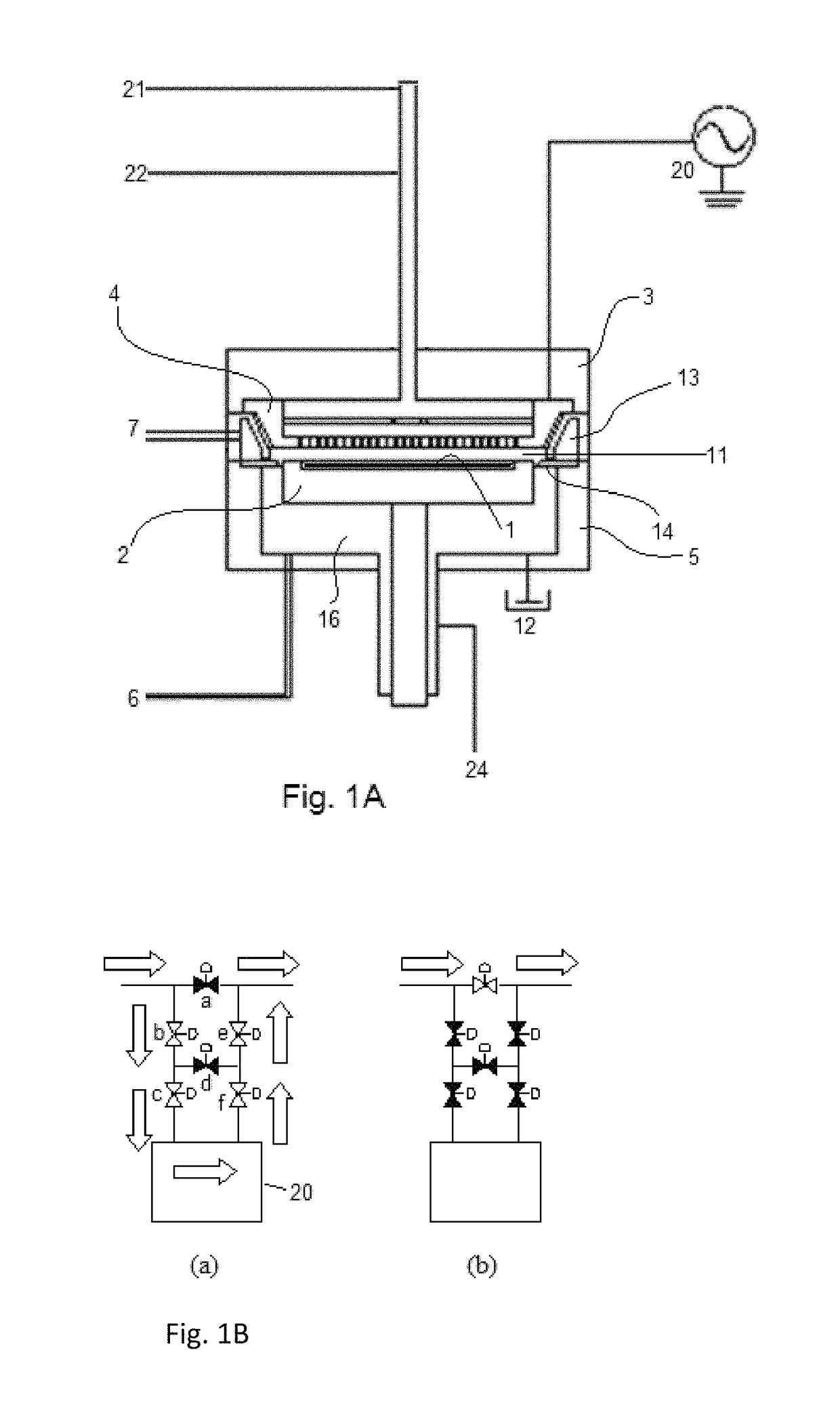
[0085]A film was formed on a substrate (having a diameter of 300 mm and a thickness of 0.7 mm) having trenches with a width (opening) of approximately 30 nm and a depth of approximately 85 nm (with an aspect ratio of about 3), by PEALD, using a sequence illustrated in FIG. 3, one cycle of which was conducted under conditions shown in Table 4 (process cycle) below using the PEALD apparatus illustrated in FIG. 1A and a gas supply system (FPS) illustrated in FIG. 1B. The resultant films were analyzed in terms of wet etch rate and conformality. The results are shown in FIG. 16. FIG. 16 is a table showing wet etching results of films deposited by PEALD according to Comparative Example 1, Example 1, Comparative Example 2, and Example 2. In the table, the cells in gray indicate that the numbers written in the cells satisfy common industrial or internal standards; “etch condition” refers to the conditions of wet etching conducted to the deposited film in ea...

example 6

[0090]In Example 6, multiple films were deposited on a silicon substrate as follows: In step 1 (St1), a first SiN film was deposited by low-pressure CVD (LPCVD) using dichlorosilane (DCS) as a precursor and N2 / H2 as reactants; in step 2 (St2), a second SiN film was deposited on the first SiN film by standard PEALD using DCS as a precursor and N2 / H2 as reactants in a manner substantially similar to that in Comparative Example 1 (except that the deposition temperature was 350° C.); in step 3 (St3), a third SiN film was deposited on the second SiN film by ramp PEALD (PEALD with ramp-down reactant flow is referred to as “ramp PEALD”) using DCS as a precursor and N2 / H2 as reactants in a manner substantially similar to that in Example 1 (except that the deposition temperature was 350° C.); in step 4 (St4),), a fourth SiN film was deposited on the third SiN film by PEALD using H2SiI2 as a precursor and N2 / H2 as reactants at a temperature of 350° C. in a manner similar to that in Example 1 ...


PUM

PropertyMeasurementUnit
diametersaaaaaaaaaa
diametersaaaaaaaaaa
depthaaaaaaaaaa

Abstract

A method is for forming a nitride or oxide film by plasma-assisted cyclic deposition, one cycle of which includes: feeding a first reactant, a second reactant, and a precursor to a reaction space where a substrate is placed, wherein the second reactant flows at a first flow ratio wherein a flow ratio is defined as a ratio of a flow rate of the second reactant to a total flow rate of gases flowing in the reaction space; and stopping feeding the precursor while continuously feeding the first and second reactants at a flow ratio which is gradually reduced from the first flow ratio to a second flow ratio while applying RF power to the reaction space to expose the substrate to a plasma. The second reactant is constituted by a hydrogen-containing compound or oxygen-containing compound.

Description

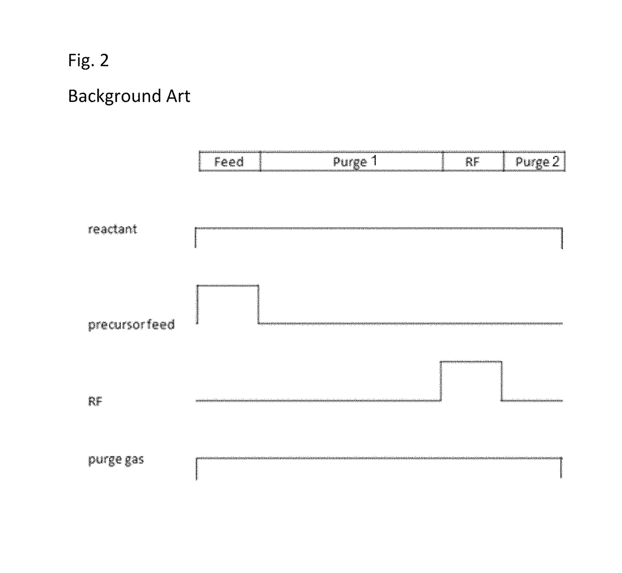
BACKGROUND OF THE INVENTIONField of the Invention[0001]The present invention generally relates to a method for forming a nitride or oxide film by plasma-assisted cyclic deposition such as plasma-enhanced atomic layer deposition (PEALD), particularly a method of plasma-assisted cyclic deposition using ramp-down flow of reactant gas.Description of the Related Art[0002]As methods of depositing conformal dielectric films on substrates, typically cyclic deposition such as atomic layer deposition (ALD) is known. A skilled artisan often uses plasma-enhanced ALD (PEALD) to form conformal dielectric films. PEALD is a deposition technology of dielectric films using chemisorption of precursors and can improve a step coverage of films depositing on recess patterns of substrates, as compared with plasma-enhanced chemical vapor deposition (PECVD). Further, as another plasma-assisted cyclic deposition, cyclic PECVD is also used for depositing conformal dielectric films. However, when depositing a ...

Claims


Application Information

Patent Timeline
Patent Type & Authority Patents(United States)
IPC IPC(8): H01L21/02C23C16/505C23C16/455C23C16/40C23C16/34
CPCH01L21/0228H01L21/0217H01L21/02164H01L21/02274H01L21/0234C23C16/505C23C16/45527C23C16/345C23C16/401C23C16/402C23C16/45536C23C16/513C23C16/45523C23C16/45542H01L21/02211H01L21/02219C23C16/56H01J37/32449H01J37/32174
Inventor BLANQUART, TIMOTHEE JULIEN VINCENT
Owner ASM IP HLDG BV
Learn More