Current and aeration system for wastewater plant

a wastewater plant and aeration system technology, applied in the direction of multi-stage water/sewage treatment, other chemical processes, separation processes, etc., can solve the problems of deterioration of the wastewater treatment process, sludge disposal presents an ecological problem, and failure of air flow in the aeration chamber, so as to minimize the formation and accumulation of sludge

Inactive Publication Date: 2006-07-25
JERRY L MCKINNEY 2002 TRUST
View PDF31 Cites 4 Cited by
  • Summary
  • Abstract
  • Description
  • Claims
  • Application Information

AI Technical Summary

Benefits of technology

[0019]A preferred embodiment of the current invention includes the use of an aerobic wastewater treatment plant with an inverted truncated conical partition dividing the aeration chamber from the clarifier chamber. A preferred embodiment uses no deflector under the clarifier chamber. The diffuser forces a pattern of circulation which produces exposure to oxygen to all fluid in the aeration chamber as shown in FIG. 4 and minimizes the formation and depositing of sludge on the bottom of the plant.

Problems solved by technology

One problem associated with aerobic wastewater treatment plants is the failure of the flow of air in the aeration chamber to keep some of the solids from continuously settling to the bottom, where they build up a layer of sludge in the aeration and clarifier chamber, requiring periodic removal.
It is desirable that a minimum of sludge removal be required since, in addition to the high maintenance requirement, disposal of the sludge presents an ecological problem.
An accumulation of sludge within the unit further results in a deterioration of the wastewater treatment process because the high concentration of bacteria in the sludge rapidly consumes the available oxygen in the immediately surrounding water, whereupon, the bacteria begins to break down nitrogen compounds in the sludge to release bonded oxygen.
This results in a release of nitrogen gas, which rises to the surface producing scum and disrupting the bacterial conversion.
Wastewater treatment plants of all shapes suffer from an accumulation of sludge in the tank.
Dead spots may also occur with the use of diffusers in two or more locations due to the interference pattern produced in the circulation or currents by the diffusers.
It has been determined, that sludge tends to accumulate at the base of deflectors and, even worse, directly below the clarifier chamber.
When the sludge is below the clarifier chamber, the nitrogen bubbles up into the clarifier chamber producing scum and interfering with the operation of the clarifier.
While the use of diffusers in multiple locations necessarily creates the problem of circulatory dead spots where sludge accumulates, this problem is accentuated since air entering into multiple lines is not emitted evenly.

Method used


Image

  • Current and aeration system for wastewater plant
  • Current and aeration system for wastewater plant
  • Current and aeration system for wastewater plant

Examples


Embodiment Construction

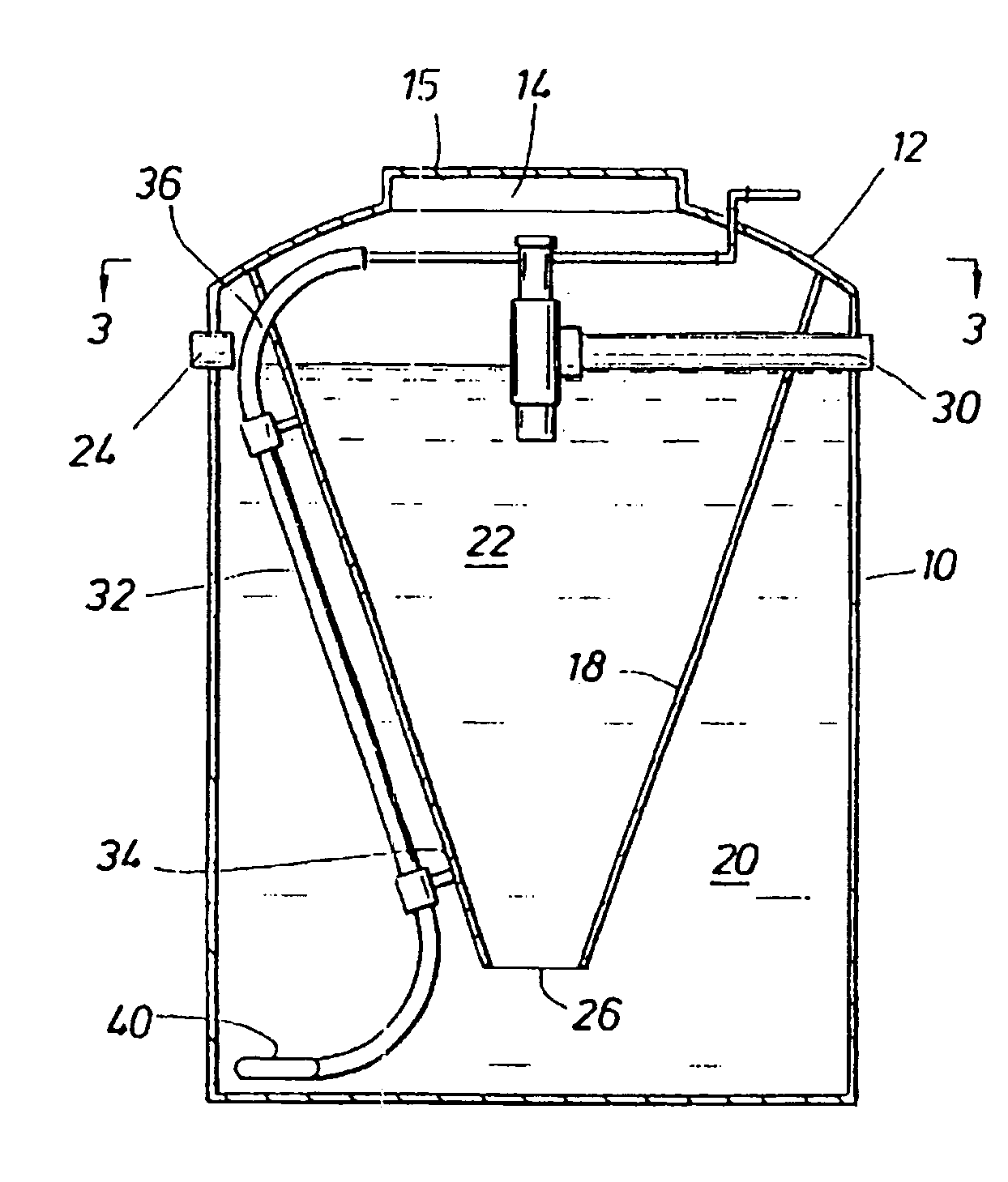
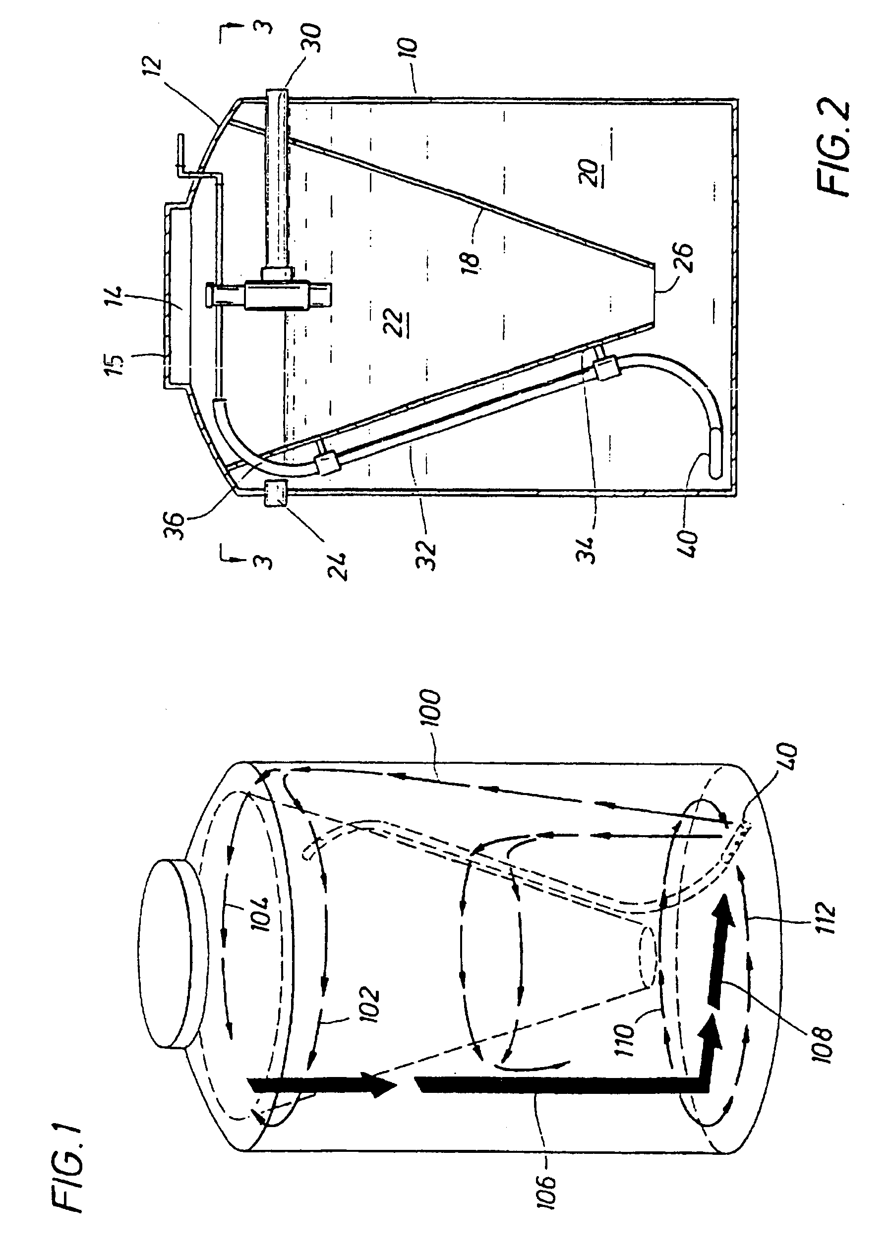
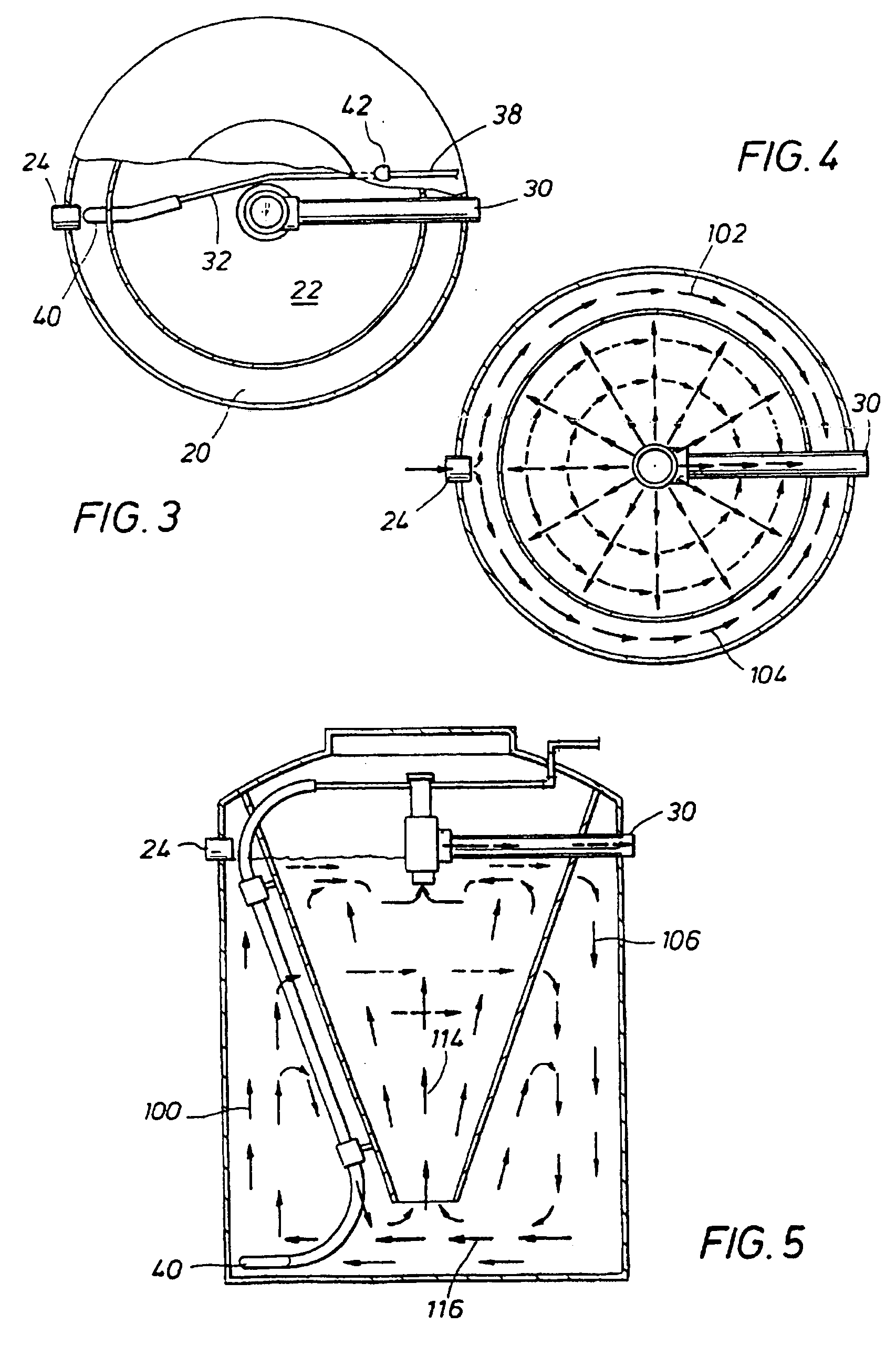
[0028]The water treatment plant of a preferred embodiment shown in the drawings includes cylindrical tank 10 with dome-shaped upper end 12. Opening 14 is located in the upper end to provide access to the inside of the tank. Usually, the tank is buried in the ground so that only opening 14 and its cover 15 are above ground.

[0029]Inside the tank is partition 18 that is shaped like an inverted, truncated, cone. The upper end of the partition is attached to dome-shaped upper end 12. This partition divides the tank into two chambers, aeration chamber 20 and clarifier chamber 22.

[0030]In operation, wastewater from the residence or facility to which the plant is connected enters the aeration chamber through inlet 24. Flow through the plant is a result of hydrostatic pressure. The water entering inlet 24 will increase the hydrostatic head in aeration chamber 20 causing water to flow into opening 26 in the bottom of the clarifier chamber. This causes the water in the clarifier chamber to mov...


PUM

PropertyMeasurementUnit
surface areaaaaaaaaaaa
rate of reductionaaaaaaaaaa
concentrationaaaaaaaaaa

Abstract

A defined current and aeration system for the aeration chamber of an aerobic wastewater treatment plant is disclosed. It includes the release of oxygenation gas or air into the aeration chamber through a diffuser or the like at a position such that the air injected into the tank provides the necessary amount of oxygen for aerobic bacterial digestion of the waste while creating a current or circulation pattern in the chamber that forces every portion of the fluid within the aeration chamber into circulation thus preventing the accumulation of solids as sludge in the wastewater treatment plant.

Description

BACKGROUND OF THE INVENTION[0001]This invention relates to an improved system for supplying air to the aeration chamber of an aerobic wastewater treatment plant.[0002]In remote areas, newly developed subdivisions, or other locations where a municipal sewer system is not available, small anaerobic or aerobic wastewater treatment plants are used to handle the wastewater produced. Septic tanks use anaerobic bacteria to convert the organic solid waste in the wastewater stream. Usually, however, most of the organic solids settle as sludge to the bottom of the septic tank and must be pumped out periodically.[0003]Aerobic wastewater treatment plants use “extended aeration” to efficiently encourage aerobic bacteria growth. Extended aeration includes contacting the wastewater with a large number of small bubbles of oxygen-carrying gas, thus maximizing the surface area for oxygen transfer. Air or oxygen is generally pumped into the tank through diffusers that break up the air into thousands o...

Claims


Application Information

Patent Timeline
Patent Type & Authority Patents(United States)
IPC IPC(8): C02F3/00C02F3/12C02F3/20
CPCC02F3/1242C02F3/20Y02W10/10
Inventor MCKINNEY, JERRY
Owner JERRY L MCKINNEY 2002 TRUST
Why Eureka
Try Eureka