Sterilization by low energy electron beam

a low-energy electron beam and sterilization technology, applied in the field of sterilization, can solve the problem of limited effect rang

Inactive Publication Date: 2007-05-29
USHIO AMERICA
View PDF14 Cites 21 Cited by
  • Summary
  • Abstract
  • Description
  • Claims
  • Application Information

AI Technical Summary

Benefits of technology

[0011]A plurality of electron beam tubes can be arranged in a spatial pattern to create a composite plasma cloud which will eliminate any hidden surfaces or “shadows” of three dimensional objects that have complex surfaces. Also, a plurality of electron ...

Problems solved by technology

Without introduction of helium an electron beam “plasma cloud” can still exist, but it...

Method used


Image

  • Sterilization by low energy electron beam
  • Sterilization by low energy electron beam
  • Sterilization by low energy electron beam

Examples


Embodiment Construction

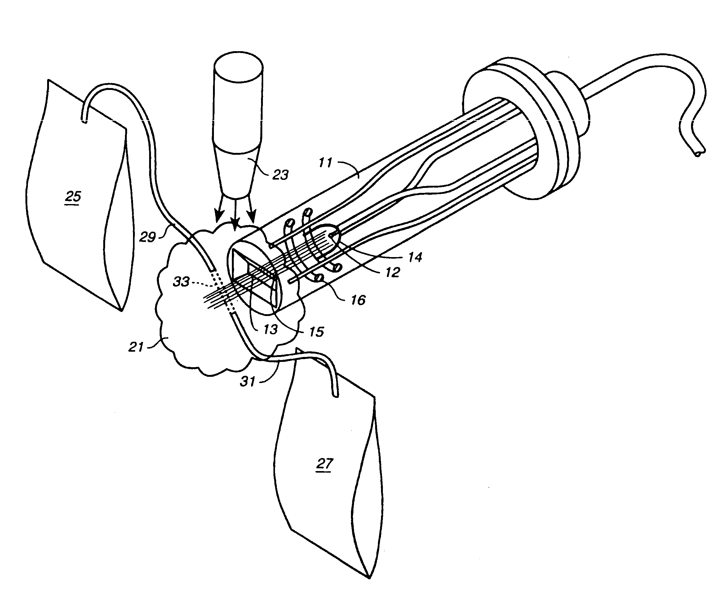
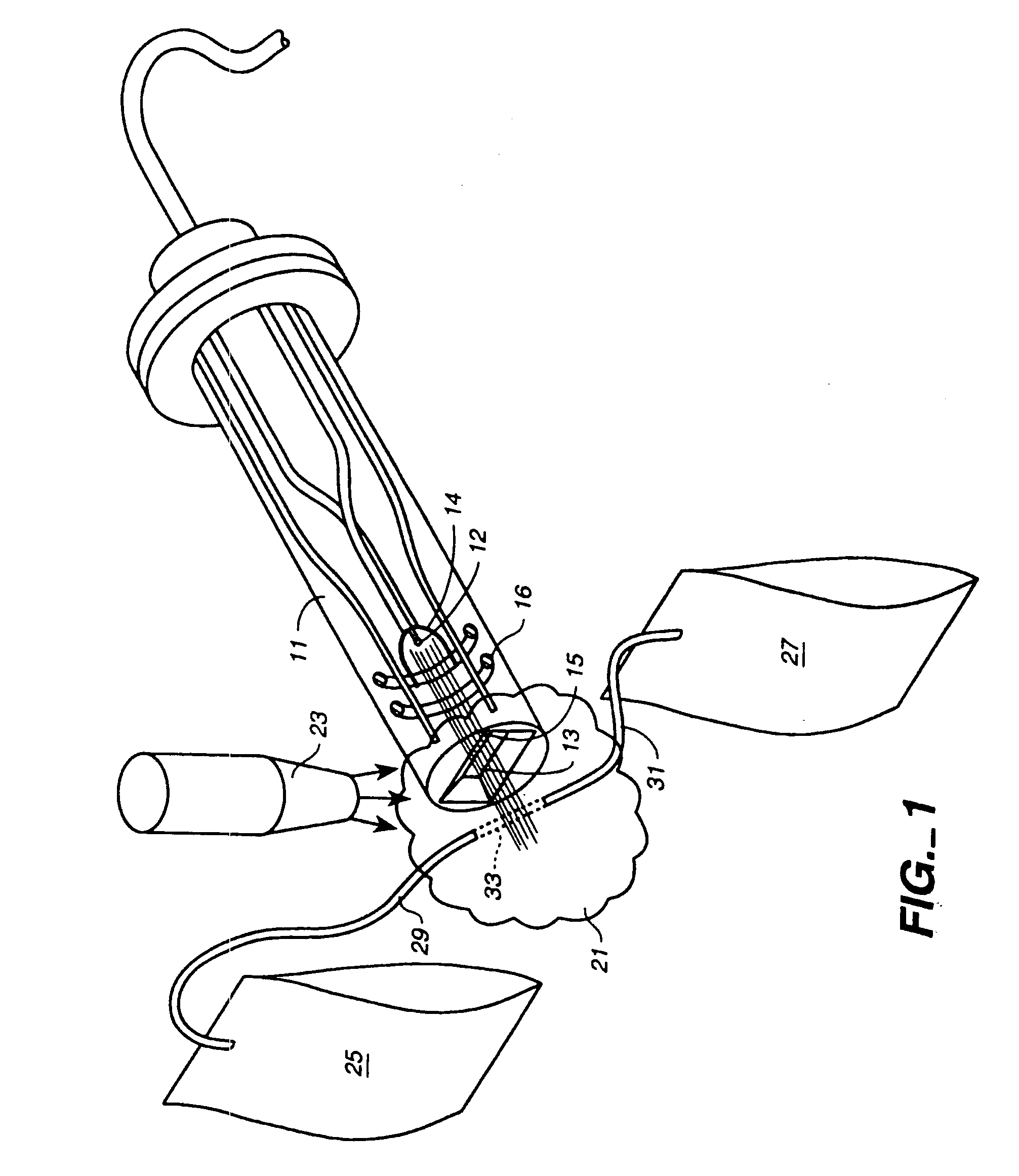
[0021]With reference to FIG. 1, an electron beam tube 11 is shown to have a window 13 through which a beam 15 emerges. Beam 15 is generated from a cathode 12 in front of an electrostatic focusing structure 14 and is further focused by a magnetic field generated by the helical coil 16. The detailed structure of beam tube 11 may be found in U.S. Pat. No. 5,612,588 to G. Wakalopulos, assigned to the assignee of the present invention. The thin window is only a few micrometers in thickness, or less, so that there is very little beam energy loss in penetrating the window. The window is preferably made of a material having a low atomic number so that electrons can readily penetrate the material, but gas molecules can not. This allows the interior of the tube to be at vacuum pressure while the outside of the tube is at ambient pressure, usually atmospheric pressure. The window is maintained at ground potential for safety reasons, while the cathode is maintained at a negative potential, for ...


PUM


Abstract

A sterilization apparatus wherein one or more electron beam tubes are used to direct electron beams into an ambient gaseous environment to create an electron plasma cloud into which non-sterile target objects may be moved. The electron plasma cloud is formed by interaction of the electron beam with the ambient atmosphere. Helium or other like gaseous may be used to expand the effective volume of the electron plasma cloud. Manipulators are used to move target objects in the electron plasma cloud, exposing non-sterile surfaces to the cloud and then joining the surfaces together where appropriate. The beam tube used to generate the electron beam has a thin low energy absorbing window which allows relatively low energy beams to be used, minimizing damage to materials within the surface of the target objects.

Description

TECHNICAL FIELD[0001]The invention relates to beam sterilization of surfaces of objects and, more particularly, to sterilization which relies mainly on electron beam interaction with surfaces of objects.BACKGROUND ART[0002]In the fields of medicine, pharmaceutical production, and food processing there is a critical need for sterilization to protect against the danger of harmful microorganisms. Most of the sterilization methods currently in use require the sterilizing agent to systemically permeate the article being sterilized. These methods include heat sterilization, where the object to be sterilized is subjected to heat and pressure, such as in an autoclave. The heat and pressure penetrates though the object being sterilized and after a sufficient time will kill the harmful microorganisms. Gases such as hydrogen peroxide or ethylene oxide have also been used to sterilize objects. For the complete sterilization of an object, the gas must permeate the entire object. An alternate ste...

Claims


Application Information

Patent Timeline
IPC IPC(8): H01J37/00H01J37/30H01J37/301A61L2/08H01J37/32H05H1/24
CPCA61L2/087A61L2202/24H01J37/32009H01J37/3233H01J2237/335H05H2245/36
Inventor WAKALOPULOS, GEORGEURGILES, EDUARDO R.BOND, PETER
Owner USHIO AMERICA
Why Eureka
Try Eureka