Flow regulated pressure swing adsorption system

a pressure swing and adsorption technology, applied in the field of separation, can solve the problems of inability to mechanically immobilize the adsorbent bed, the logic and control of the valve is then greatly complicated, and the inability to achieve the assembly of the rotary adsorbent bed

Inactive Publication Date: 2008-01-22
AIR PROD & CHEM INC
View PDF151 Cites 75 Cited by
  • Summary
  • Abstract
  • Description
  • Claims
  • Application Information

AI Technical Summary

Benefits of technology

[0031]The present invention achieves pressurization and depressurization steps primarily by gas exchanges between the adsorbent beds. Steps entailing exchange of gas enriched in the second component between adsorbent beds will be described as light reflux steps. A predetermined logical sequence of the process steps will be established by rotary distributor valves, while flow regulation controls will enable satisfactory operation under varied process conditions and under varied cycle frequencies so that required product purity, recovery and output can be achieved by a simple control strategy.
[0038](B) withdrawing a flow of gas enriched in the second component (light reflux gas) from the second end of the adsorbent bed through the second distributor valve, so as to depressurize the adsorbent bed from the higher pressure toward an equalization pressure less than the higher pressure, while controlling the flow so that the pressure in the bed approaches the equalization pressure within an equalization time interval, and also controlling the flow so as to limit the peak flow velocity exiting the second end of the adsorbent bed in that time interval so as to avoid damaging the adsorbent,
[0039](C) withdrawing a flow of gas enriched in the second component (light reflux gas) from the second end of the adsorbent bed through the second distributor valve, so as to depressurize the adsorbent bed from approximately the equalization pressure to an intermediate pressure less than the equalization pressure and greater than the lower pressure, while controlling the flow so that the pressure in the bed reaches approximately the intermediate pressure within a cocurrent blowdown time interval, and also controlling the flow so as to limit the peak flow velocity exiting the second end of the adsorbent bed in that time interval so as to avoid damaging the adsorbent,
[0040](D) withdrawing a flow of gas enriched in the first component (countercurrent blowdown gas) from the first end of the adsorbent bed through the first distributor valve, so as to depressurize the adsorbent bed from approximately the intermediate pressure to approach the lower pressure, while controlling the flow so that the pressure in the bed approaches the lower pressure within a countercurrent blowdown time interval, and also controlling the flow so as to limit the peak flow velocity adjacent the first end of the adsorbent bed in that time interval so as to avoid damaging the adsorbent,
[0042](F) supplying a flow of gas enriched in the second component (light reflux gas) from the second distributor valve to the bed, so as to repressurize the adsorbent bed from approximately the lower pressure to approach the equalization pressure, while controlling the flow so that the pressure in the bed approaches the equalization pressure within an equalization time interval, and also controlling the flow so as to limit the peak flow velocity entering the first end of the adsorbent bed in that time interval so as to avoid damaging the adsorbent, the flow of gas enriched in the second component from the second distributor valve being withdrawn from another of the adsorbent beds which is undergoing equalization step (B) of the process,
[0043](G) supplying a flow of gas enriched in the second component (light reflux gas) from the second distributor valve to the bed, so as to repressurize the adsorbent bed from the equalization pressure to approach the higher pressure, while controlling the flow so that the pressure in the bed approaches the higher pressure within a repressurization time interval, and also controlling the flow so as to limit the peak flow velocity entering the second end of the adsorbent bed in that time interval so as to avoid damaging the adsorbent, the flow of gas enriched in the second component from the second distributor valve being withdrawn from another of the adsorbent beds which is undergoing feed step (A) of the process,

Problems solved by technology

With a greater number of beds, multiple pressure equalization steps can be achieved, although the valve logic and controls are then greatly complicated.
For large industrial PSA systems, mechanical immobilization of the adsorbent beds has not been practicable.
However, a rotary adsorbent bed assembly may be impracticable for large PSA units, owing to the weight of the rotating assembly.
Also, when separating gas components which are highly inflammable or toxic, the rotary adsorbent bed assembly would need to be completely enclosed in a containment shroud to capture any leakage from large diameter rotary seals.
However, these prior art devices have limited utility except in small scale applications, owing to their lack of control flexibility.
Since valve timing logic and port orifice sizing of the multiport valves are fixed rigidly in these prior art inventions, there is no provision for flow control to provide operational adjustment under changing feed conditions or during intervals of reduced product demand, or for performance optimization.
This inflexibility of control is most limiting for those of the cited prior art inventions which use multiport valves to exchange gas between a pair of beds, and across a pressure difference between that pair of beds.
Once the internal orifice apertures of the rotary valves and piping connections have been fixed, the prior art PSA cycle using multiport valves could only operate correctly between given high and low pressures at one cycle frequency with a given feed composition, and would have no means for operational adjustment to optimize cycle performance.
Hence, prior art PSA devices with multiport valves would be unable to operate at much reduced cycle frequency during periods of reduced demand for purified product.
If the cycle frequency is moderately too high, the apparatus will release a larger exhaust flow, achieving higher than desired purity and lower than desired recovery of the light product.
If the cycle frequency is much too high, mass transfer effects may degrade performance to result in unsatisfactory light product purity as well as low recovery.
None of the cited prior art for pressure swing adsorption with multiport valves addresses the combined need for adjustable cycle frequency control and adjustable flow controls for gas exchanges between pairs of adsorbent beds.
Hence, these devices as disclosed have the operational limitation that they cannot be operated at significantly varied conditions of cycle frequency and pressure.
The above cited PSA devices with multiport distributor valves lack any control means for making adjustments between the pressure intervals taken up by the different steps of the cycle.
A further limitation of the prior art for PSA devices using multiport valves is the lack of control means to establish relatively smooth and constant flow over each step.

Method used


Image

  • Flow regulated pressure swing adsorption system
  • Flow regulated pressure swing adsorption system
  • Flow regulated pressure swing adsorption system

Examples


embodiment 1

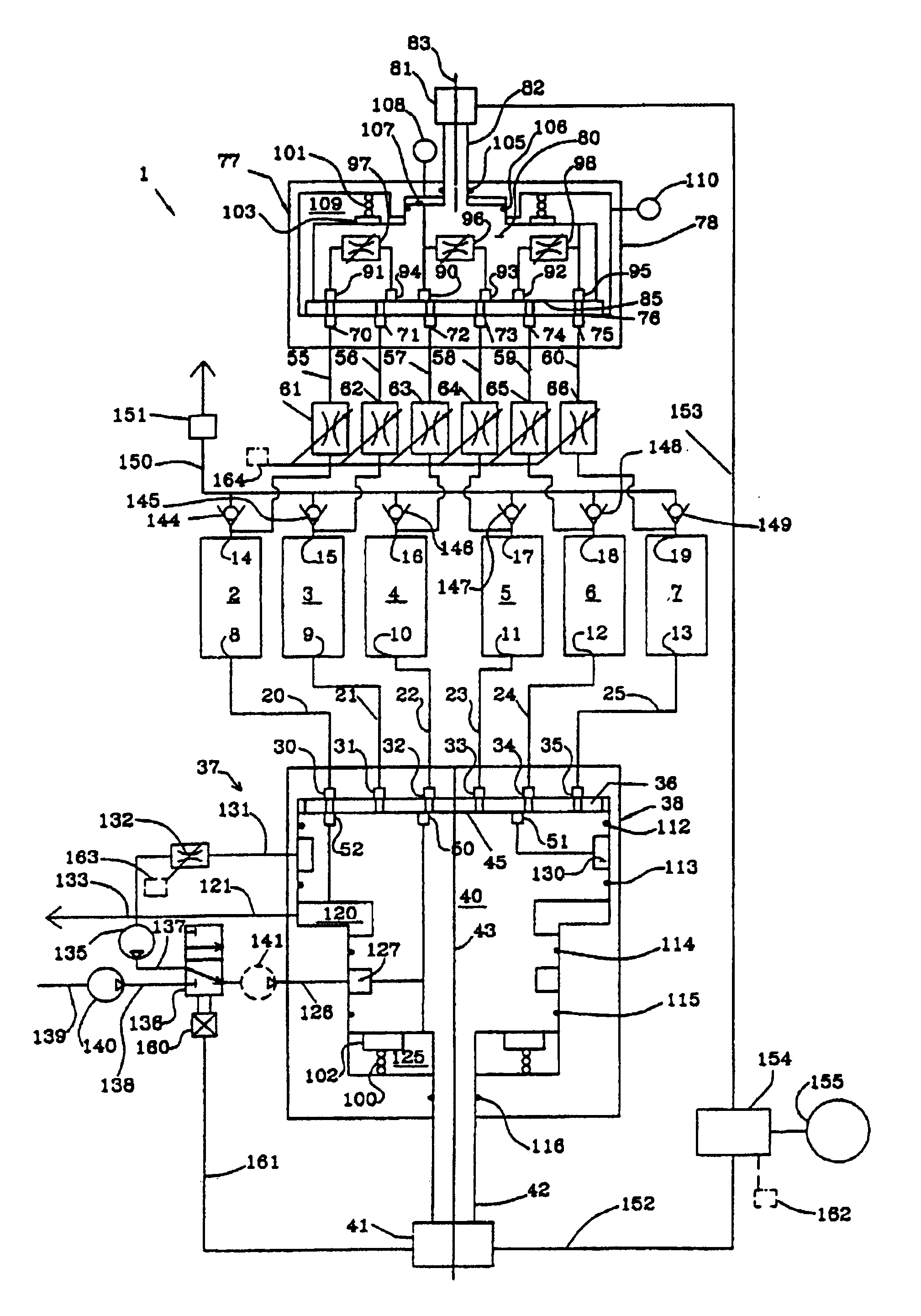
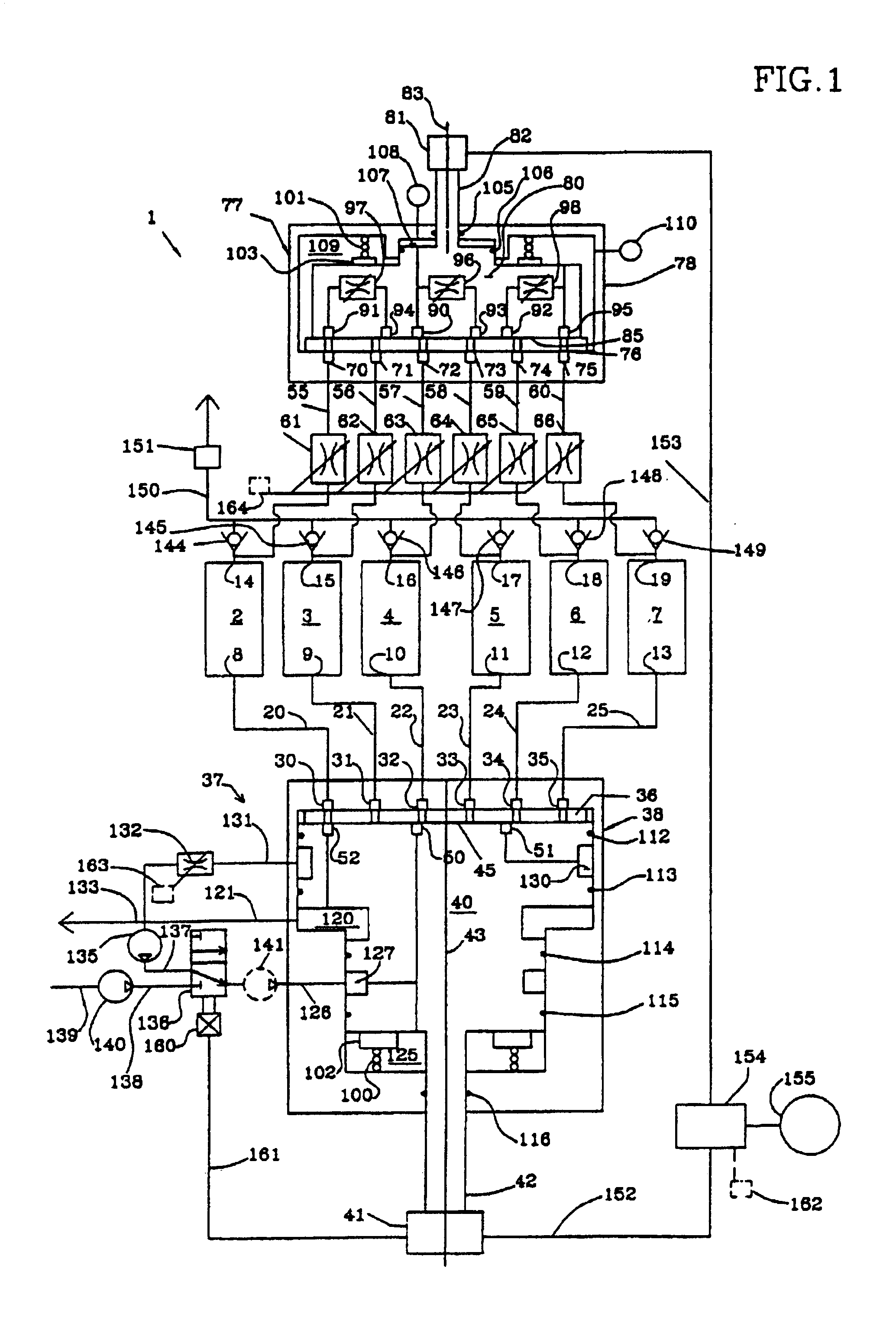
[0170]FIG. 10 is a schematic drawing of an alternative second distributor valve 400 with control means for the adjustable orifices of the rotor as configured for embodiment 1 of FIG. 1. Adjustable orifices 96-98 are provided as throttle valves mounted in rotor 80, each with identical or similar external actuation means, described here in detail for adjustable orifice 97. Light reflux withdrawal port 91 communicates by conduit 401 to upstream valve chamber 402. Chamber 402 is penetrated by valve stem 405 with coaxial needle 406 aligned with valve seat 408. The adjustable throttle valve orifice is defined between needle 406 and seat 408, and provides fluid communication with downstream valve chamber 410 which in turn communicates by conduit 412 to light reflux return port 94.

[0171]Drive end 414 of valve stem 405 is isolated from process fluid by seal 415, and is provided with a drive pin 416 penetrating a drive slot 417 in rotor 80. Slot 417 has axial clearance for pin 416, sufficient...

embodiment 450

[0174]An alternative embodiment 450 of the second distributor valve uses fluid transfer chambers between the rotor 80 and the stator housing 78, so that the adjustable orifices can be provided as throttle valves external to the stator housing.

[0175]On a common sealing diameter, rotary seals 451, 452, 453, 454 and 455 mutually isolate chamber 107 communicating in rotor 80 to light reflux withdrawal port 90 at substantially the higher pressure, transfer chamber 461 communicating to light reflux return port 93, transfer chamber 462 communicating to light reflux withdrawal port 91, transfer chamber 463 communicating to light reflux return port 94, transfer chamber 464 communicating to light reflux withdrawal port 92, and chamber 109 communicating to light reflux return port 95 at substantially the lower pressure. Adjustable orifice 96 is provided as throttle valve 471 communicating through stator housing 78 to chambers 107 and 461. Adjustable orifice 97 is provided as throttle valve 472...

embodiment 600

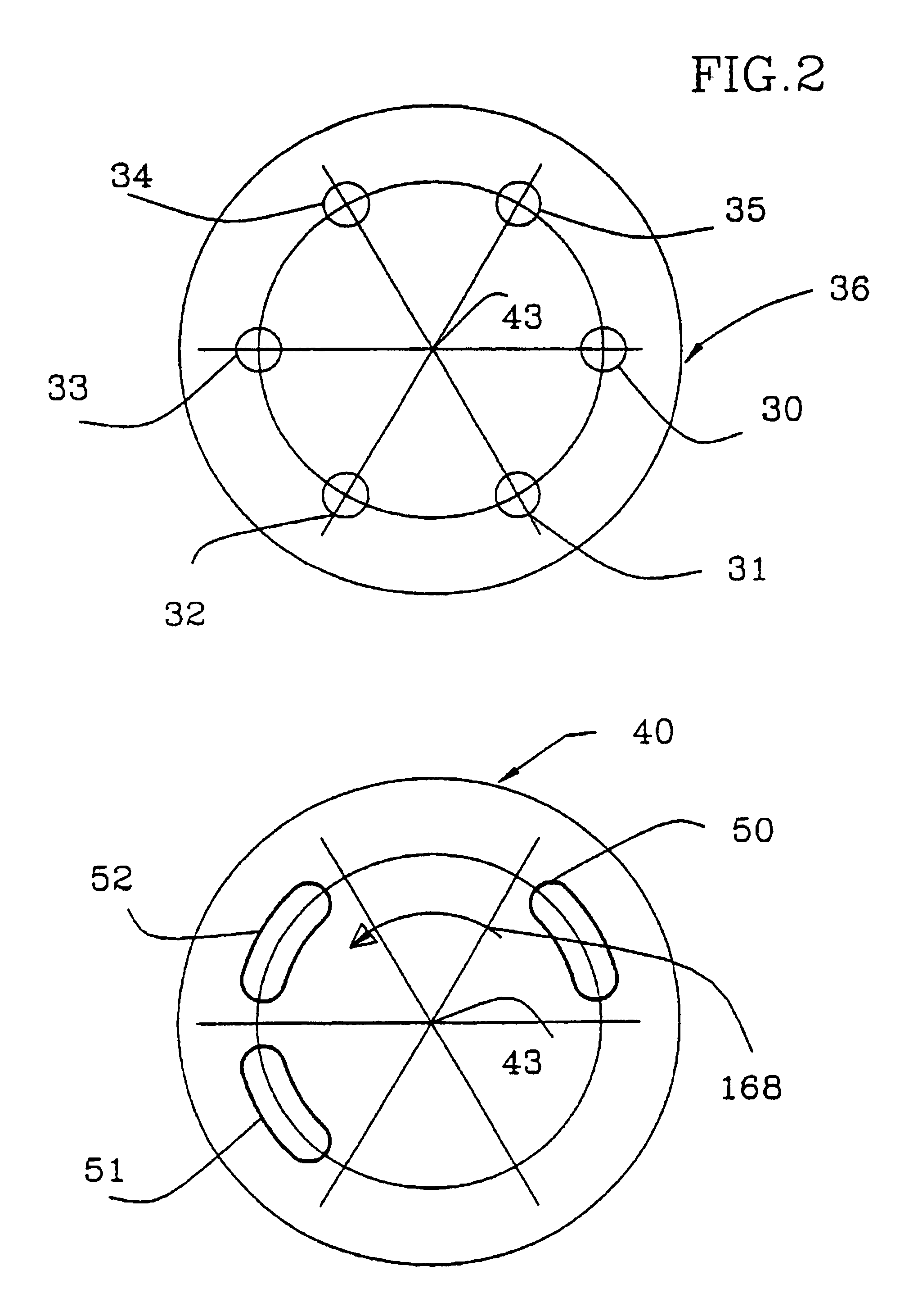
[0189]FIGS. 13 and 14 show an alternative embodiment 600 of the first distributor valve in which approximate radial balance of the contact pressure distribution on the valve surface 45 is achieved by communicating the pressure distribution on the valve surface to a plurality of axially aligned loading pistons 601-607 disposed in a coaxial annular ring around the axis 43 within the valve rotor at a radius approximately equal to or somewhat greater than the radius of the function ports. Each of the pistons 603-607 is pressurized by the local pressure at its axially projected position on the valve surface (typically corresponding to a function port), and is sealed by a piston ring 608 in a cylinder 613-617 in rotor 40, with each cylinder parallel to axis43. The loading pistons are reacted on a rotating thrust plate 620, bearing against stationary thrust pad 621 of self-lubricating material. Thrust pad 621 is supported within stator housing 38, normal to the axis of rotation. Each of th...


PUM

PropertyMeasurementUnit
pressureaaaaaaaaaa
pressureaaaaaaaaaa
pressureaaaaaaaaaa

Abstract

Pressure swing adsorption (PSA) separation of a gas mixture is performed in an apparatus with a plurality of adsorbent beds. The invention provides rotary multiport distributor valves to control the timing sequence of the PSA cycle steps between the beds, with flow controls cooperating with the rotary distributor valves to control the volume rates of gas flows to and from the adsorbent beds in blowdown, purge, equalization and repressurization steps.

Description

[0001]The present application is a continuation of co-pending U.S. Reissue patent application No. 10 / 150,784, entitled “Flow Regulated Pressure Swing Adsorption System,” filed on May 16, 2002, and to be issued as U.S. Pat. No. RE38,493 on Apr. 13, 2004, which is a reissue of U.S. patent application No. 08 / 637,176, entitled “Flow Regulated Pressure Swing Adsorption System,” filed Apr. 24, 1996, now U.S. Pat. No. 6,063,161, the disclosures of which are hereby incorporated by reference.<?insert-end id="INS-S-00001" ?>TECHNICAL FIELD[0002]The invention relates to separations conducted by pressure swing adsorption (PSA). The present invention provides simplified controls, with enhanced flexibility of control adjustment through flow regulation under changing operating conditions.BACKGROUND ART[0003]Gas separation by pressure swing adsorption is achieved by coordinated pressure cycling and flow reversals over adsorbent beds which preferentially adsorb a more readily adsorbed componen...

Claims


Application Information

Patent Timeline
Patent Type & Authority Patents(United States)
IPC IPC(8): B01D53/047B01D53/04
CPCB01D53/0446B01D53/047B01D2253/108B01D2253/25B01D2256/16B01D2257/504B01D2258/0208B01D2259/40005B01D2259/4003B01D2259/40037B01D2259/40067B01D2259/4062Y10T137/86863Y02C20/40
Inventor KEEFER, BOWIE G.DOMAN, DAVID G.
Owner AIR PROD & CHEM INC
Why Eureka
Try Eureka