
Output circuit for adjusting output voltage slew rate

a technology of output voltage and output voltage, applied in the field of output circuits, can solve the problems of serious impact on the operation of the circuit, difficulty in adjusting, and limited change of output voltage of pmos and nmos, so as to avoid short-circuit current

Inactive Publication Date: 2010-11-16
REALTEK SEMICON CORP
View PDF8 Cites 6 Cited by
  • Summary
  • Abstract
  • Description
  • Claims
  • Application Information

AI Technical Summary

Benefits of technology

[0007]Accordingly, it is the primary object of the present invention to provide an output circuit which is able to adjust output voltage slew rate and avoid short-circuit current.
[0008]It is another object of the present invention to provide an output circuit which is able to adjust output voltage slew rate and output current simultaneously and avoid short-circuit current.
[0010]Therefore, the present invention is able to adjust the output voltage slew rate of the output circuit by controlling the time constant of the first capacitor device and the second capacitor device.

Problems solved by technology

However, the output voltage slew rate of the output circuit characteristic of these “simple” inverters is determined by the parasitic capacitor and the loading capacitor and is difficult to be adjusted by a user with simple method.
Thus, in the situation that output signal is with high speed and high amplitude, the electromagnetic interference easily occurs, which seriously impacts the operation of the circuit.
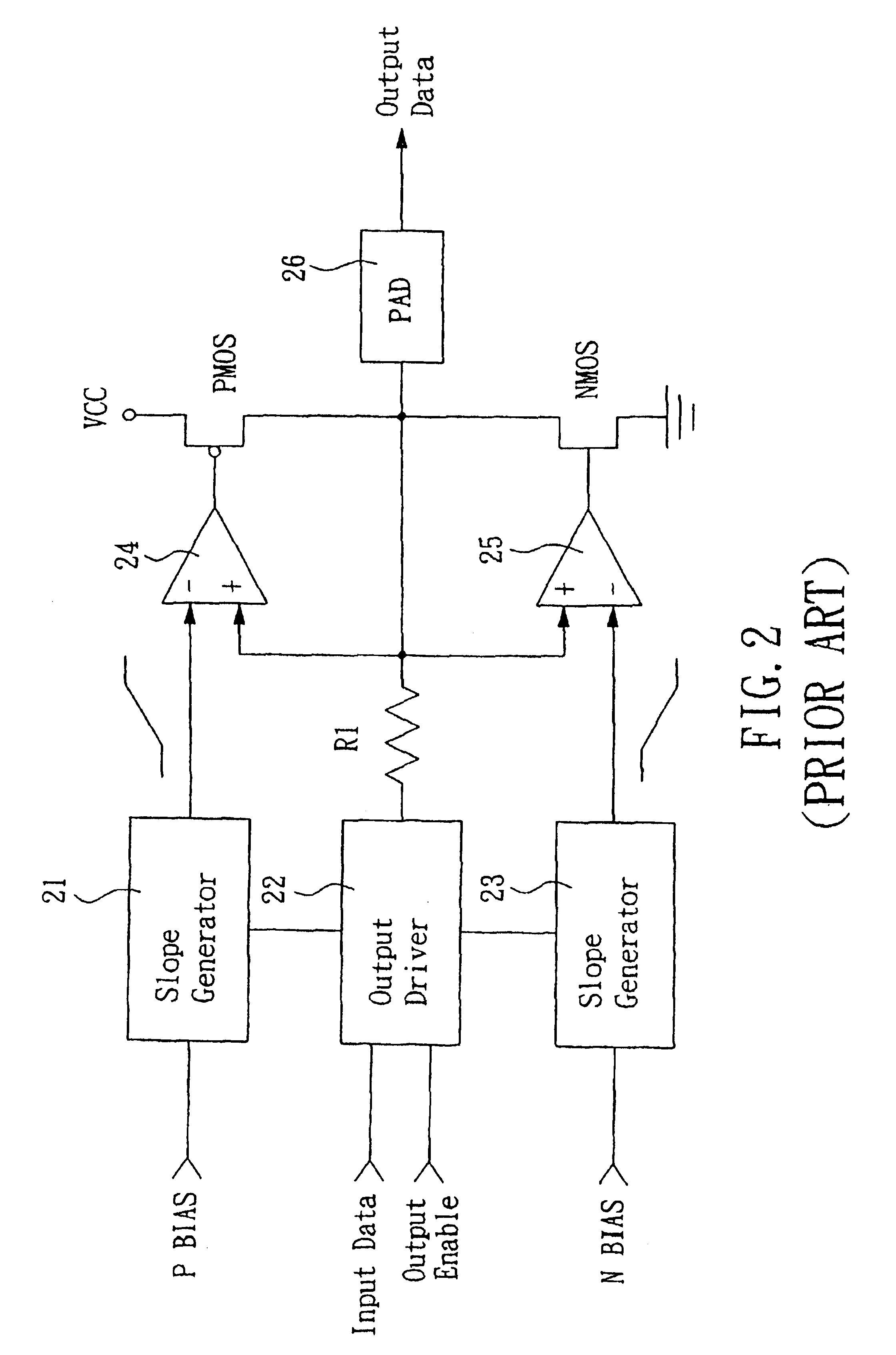
However, since the comparators 24 and 25 consist of OP, the change of the output voltage of PMOS and NMOS is limited by the bandwidth and the output voltage slew rate of OP.
When the slope signal input to OP is with higher slope, the output voltage of OP will probably generate ripple, or even cause OP unstable.
Besides the problem associated with output voltage slew rate, the output circuit 20 also comes with short-circuit current problem.
When the output voltage of the output driver 22 reaches the half of the output amplitude, PMOS and NMOS will conduct simultaneously, and which cause the circuit system to suffer short-circuit current problem that large amount of current coming through suddenly.
The problem not only causes the large amount of current extremely increase all of a sudden but also creates large amount of heat, which seriously impacts the quality and the life of the circuit.

Method used


Image

  • Output circuit for adjusting output voltage slew rate
  • Output circuit for adjusting output voltage slew rate
  • Output circuit for adjusting output voltage slew rate

Examples


Embodiment Construction

[0024]The present invention providing an output circuit for adjusting output voltage slew rate can be exemplified by the preferred embodiment as described hereinafter.

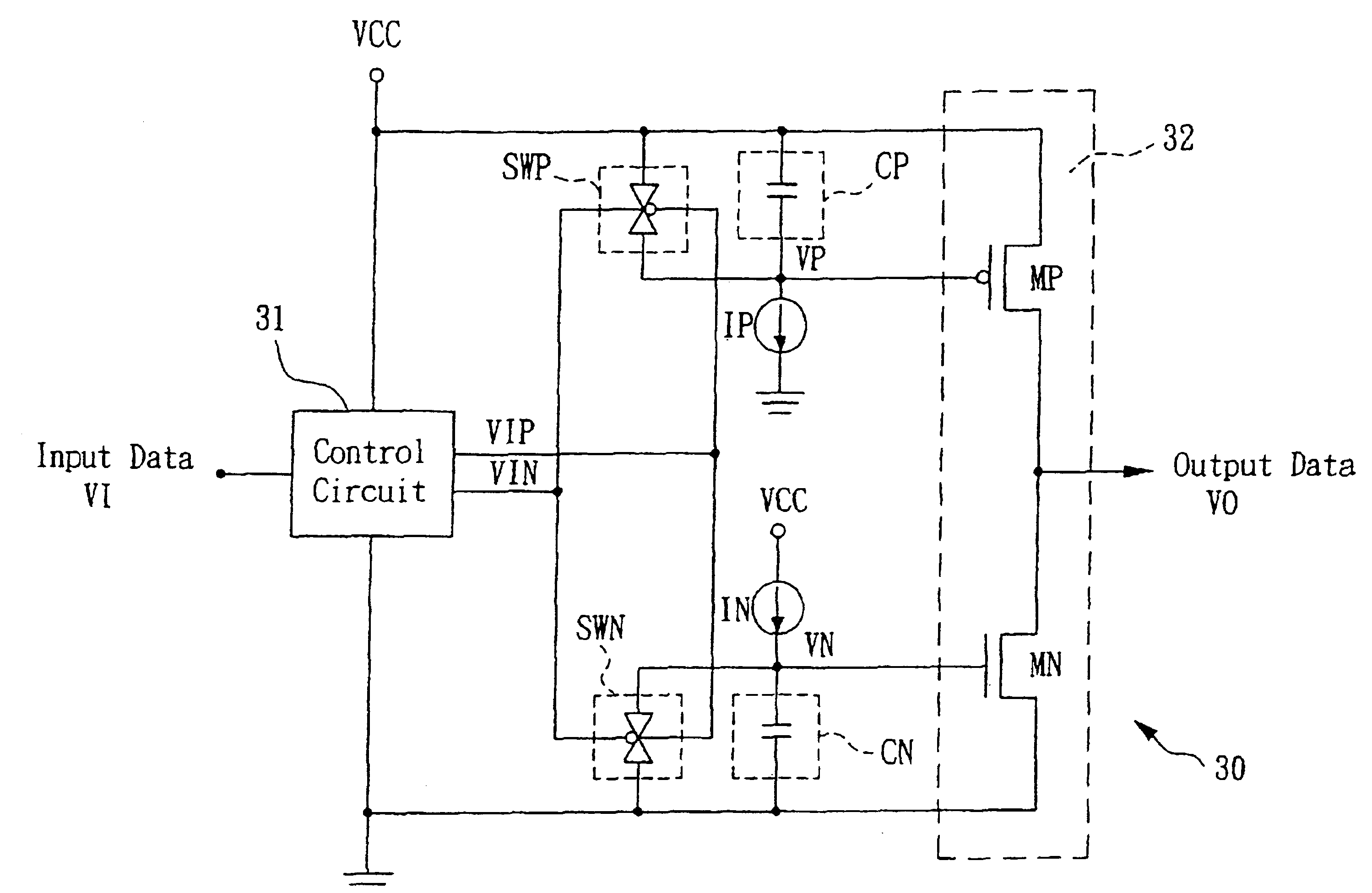
[0025]Please refer to FIG. 3, which is a schematic block diagram of the first embodiment showing an output circuit for adjusting output voltage slew rate in accordance with the present invention. In the FIG. 3, the output circuit 30 for adjusting output voltage slew rate of the present invention comprises a control circuit 31, a first switch SWP, a first capacitor CP, a first current source IP, a second switch SWN, a second capacitor CN, a second current source IN and a output control device 32.

[0026]The control circuit 31 generates a first set of control signal VIP and VIN based on an input data VI, meanwhile, the relationship of the control signals VIP and VIN are inverted. In the present invention, when the input data VI is HIGH, the control signal VIP is HIGH and the control signal VIN is LOW. The control signals V...


PUM


Abstract

The present invention discloses an output circuit that is able to adjust the output voltage slew rate and avoid short-circuit current, comprising: a control circuit for receiving an input data and generating a first set of control signals based on the input data; an output control device consisting of a first field effect transistor (FET) connected in series with a second field effect transistor (FET) and the point of connection is the output end for generating an output signal; a first capacitor having one end connected to a first working voltage and generates a first control voltage by charging / discharging on another end to control the gate of the first field effect transistor; a first switch for controlling charging / discharging of the first capacitor device based on the first set of control signals; a first current source for providing charging current for the first capacitor device; a second capacitor having one end connected to a second working voltage and generates a second control voltage by charging / discharging on another end to control the gate of the second field effect transistor; a second switch for controlling charging / discharging of the second capacitor device based on the first set of control signal; and a second current source providing charging current for the second capacitor device. The present invention adjusts output voltage slew rate of the output circuit by adjusting the time constant of the first and second capacitor devices.

Description

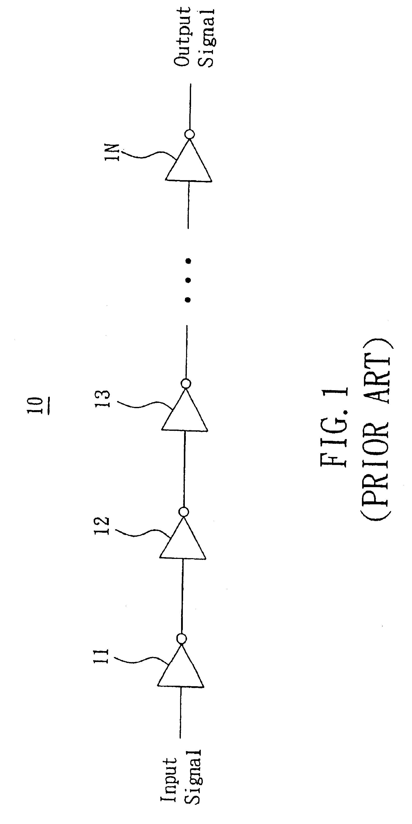
BACKGROUND OF THE INVENTION[0001]1. Field of the Invention[0002]The present invention generally relates to an output circuit which is able to adjust output voltage slew rate and output current and avoid short-circuit current. The output circuit of the present invention can apply in many different application for circuit restricted by output voltage slew rate; such as USB, to assure the properties of circuit comply with required specification.[0003]2. Description of the Prior Art[0004]Generally speaking, the signal of a circuit can be output from a simple inverter set 10; as shown in FIG. 1, which is serially connected with stage 11, stage 12, and so on to stage IN. The output circuit of such kind is pretty simple and fewer components arc required, which is very suitable for low speed, low cost application. However, the output voltage slew rate of the output circuit characteristic of these “simple” inverters is determined by the parasitic capacitor and the loading capacitor and is di...

Claims


Application Information

Patent Timeline
Patent Type & Authority Patents(United States)
IPC IPC(8): H03K5/12H03K17/16
CPCH03K17/163H03K19/00361
Inventor LEE, AN-MING
Owner REALTEK SEMICON CORP
Learn More