Projection system for EUV lithography
a projection system and lithography technology, applied in the field of microlithography objectives, can solve the problems of reducing the throughput of the entire projection apparatus, the system is very long (3000 mm), and the examples are not well suited to contemporary lithography at extreme ultraviolet wavelengths, etc., to achieve the effect of efficient masking of undesired light, easy manufacturing, and convenient mechanical achievemen
- Summary
- Abstract
- Description
- Claims
- Application Information
AI Technical Summary
Benefits of technology
Problems solved by technology
Method used
Image
Examples
first embodiment
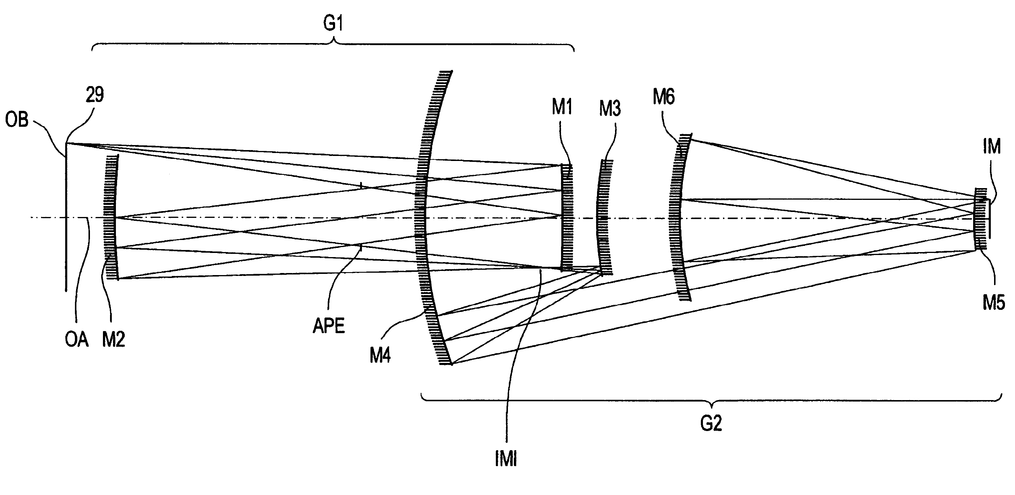
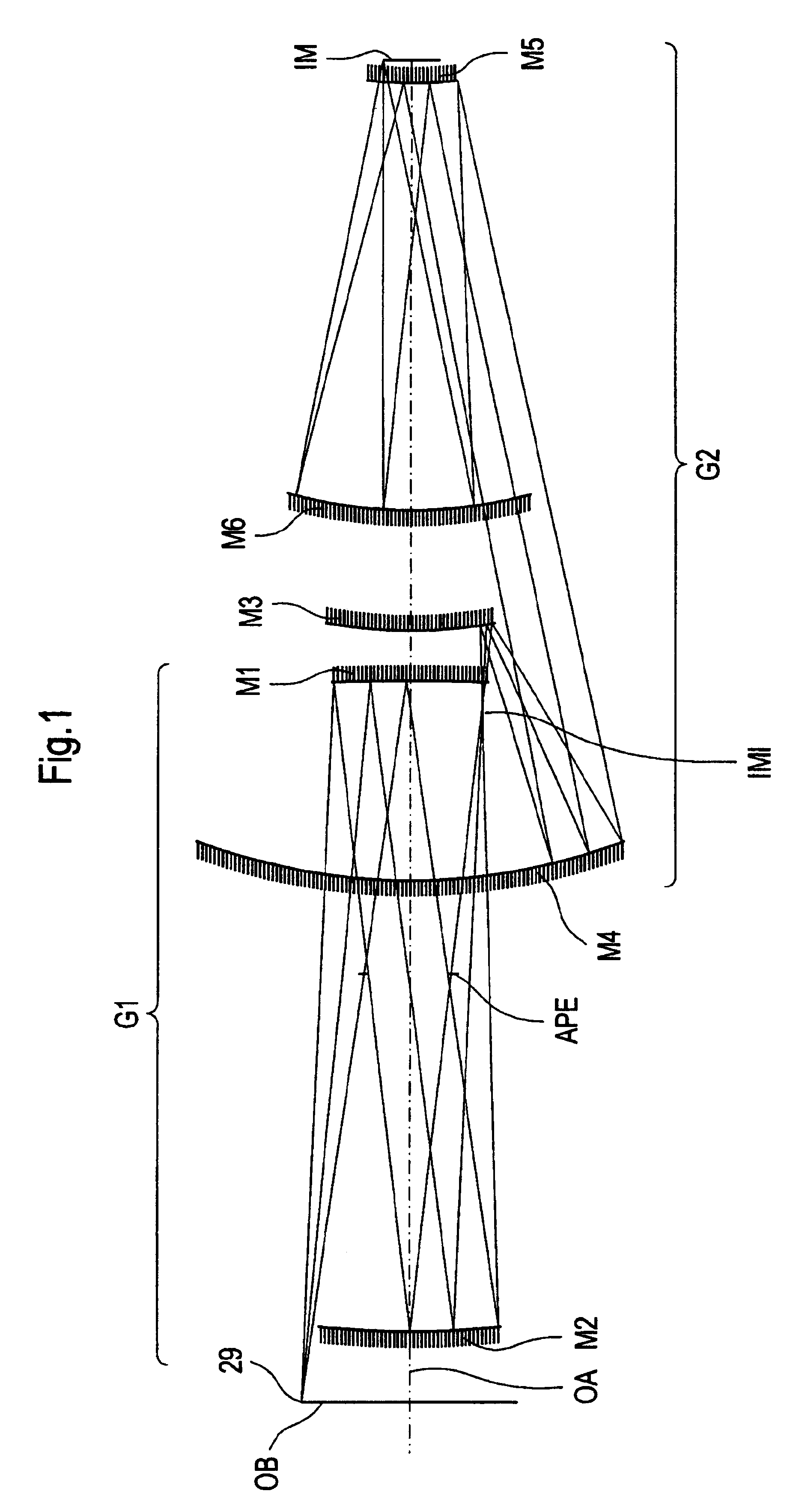
[0072]The optical prescription of FIG. 1 is listed in Table 1 and Table 2. The aspheric mirror surfaces are labeled A(1)-A(6) in the tables with A(1) corresponding to mirror M1, A(2) corresponding to mirror M2, and so on. Four additional surfaces complete the description of this illustrative and exemplary embodiment with object OB and image IM representing the planes, where in a lithographic apparatus the mask and the wafer are arranged. A surface designation is also made for the location of the aperture stop APE and intermediate image IMI. After each surface designation, there are two additional entries listing the vertex radius of curvature (R) and the vertex spacing between the optical surfaces. In this particular embodiment, each of the surfaces is rotationally symmetric conic surface with higher-order polynomial deformations. The aspheric profile is uniquely determined by its K, A, B, C, D, and E values. Each mirror uses 4th, 6th, 8th, 10th, and 12th order polynomial deformatio...
second embodiment
[0080]In addition to the features outlined by the first preferred embodiment, this second preferred embodiment teaches that the tertiary mirror M3′ may be located on the object side of the primary mirror M1′ (i.e., closer to the object OB′ than the primary mirror M1′). This feature departs drastically from the teaches of the prior art that show the tertiary mirror must be located either in close proximity to the primary mirror ('079 patent) or on the image side of the primary mirror('310 patent). This location of mirror M3′ enables a reduction in the overall length from object plane OB to image plane IM (total track length) by some 250 mm. This decrease in total track length is accomplished by shifting the tertiary mirror from the image side of the primary mirror M1′ to the object side of the primary mirror M1′ and then decreasing the distance between mirror M1′ and mirror M6′. This also allows the parent diameter of the tertiary mirror M3′ to be smaller than either the primary mirr...
third embodiment
[0087]The optical prescription for this third embodiment of FIG. 4 is listed in Table 7 and Table 7. Table 7 lists the vertex radius of curvature as well as the separation between these mirrors along the optical axis. Each mirror is aspheric and labeled A(1)-A(6) in the tables with A(1) corresponding to mirror M1″, A(2) corresponding to mirror M2″, and so on. The prescription of the aspheric surface deformation per equation (1) is listed in Table 8. Taken together with the information provided in Table 9, an illustrative and exempary description of this prefered embodiment is disclosed.
[0088]Like the first two preferred embodiments, the object OB″, e.g. a pattern on mask or reticle, will be projected to the image IM″ at 4× reduction in a ring field format with a telecentric imaging bundle (chief rays parallel to the optical axis at the image). At the image″ typically a semiconductor wafer is arranged. Table 6 provides a performance summary demonstrating that this preferred embodimen...
PUM
 Abstract
Description
Claims
Application Information
 - R&D
- Intellectual Property
- Life Sciences
- Materials
- Tech Scout
- Unparalleled Data Quality
- Higher Quality Content
- 60% Fewer Hallucinations
Browse by: Latest US Patents, China's latest patents, Technical Efficacy Thesaurus, Application Domain, Technology Topic, Popular Technical Reports.
© 2025 PatSnap. All rights reserved.Legal|Privacy policy|Modern Slavery Act Transparency Statement|Sitemap|About US| Contact US: help@patsnap.com


