Power supply for light emitting diode array

a technology of light-emitting diodes and power supplies, applied in emergency power supply arrangements, process and machine control, instruments, etc., can solve problems such as poor power factor of highly reactive power supplies, poor leakage current waveforms of input current, and use of questionable led signals. , to achieve the effect of eliminating leakage current problems

Inactive Publication Date: 2011-02-22
AGREEMENT & DECLARATION OF TRUST DATED JUNE 1 2009
View PDF175 Cites 93 Cited by
  • Summary
  • Abstract
  • Description
  • Claims
  • Application Information

AI Technical Summary

Benefits of technology

[0017]The apparatus according to the present invention also includes an adaptive clamp circuit connected to the rectifier input for eliminating leakage current problems. The adaptive clamp circuit has an input adapted to be connected to a pair of a.c. power lines, a pair of clamp circuit output lines connected to the adaptive clamp circuit input, a voltage sensing means connected across the adaptive clamp circuit input, and a controlled load means connected across the clamp circuit output lines and to the voltage sensing means. The voltage sensing means is responsive to a magnitude of a.c. voltage at the adap

Problems solved by technology

The highly dissipative nature of such linear regulators makes such use questionable in heat sensitive apparatus such as LED signals however.
Such highly reactive power supplies exhibit very poor power factors however, and may be disallowed by power utilities.
Several problems are associated with these prior art simple circuit topologies.
The input current wave forms are generally badly distorted and the power factor is poor.
Reasons for the poor power factor and high distortion relate to the discontinuous conduction of the diodes in the circuit feeding large capacitors.
This phenomenon is well understood, and plagues many small off line power supplies.
In fact, many utilities are placing limits on permissible power factor and distortion behavior of electrical devices connected to their lines.
Also, in many parts of the country, electrical generating capacity is at its limits, and new capacity cannot be added because of environmental concerns.
This strong interest in LED signals as an important energy conservation resource is clouded however by the poor power factor performanc

Method used


Image

  • Power supply for light emitting diode array
  • Power supply for light emitting diode array
  • Power supply for light emitting diode array

Examples


Embodiment Construction

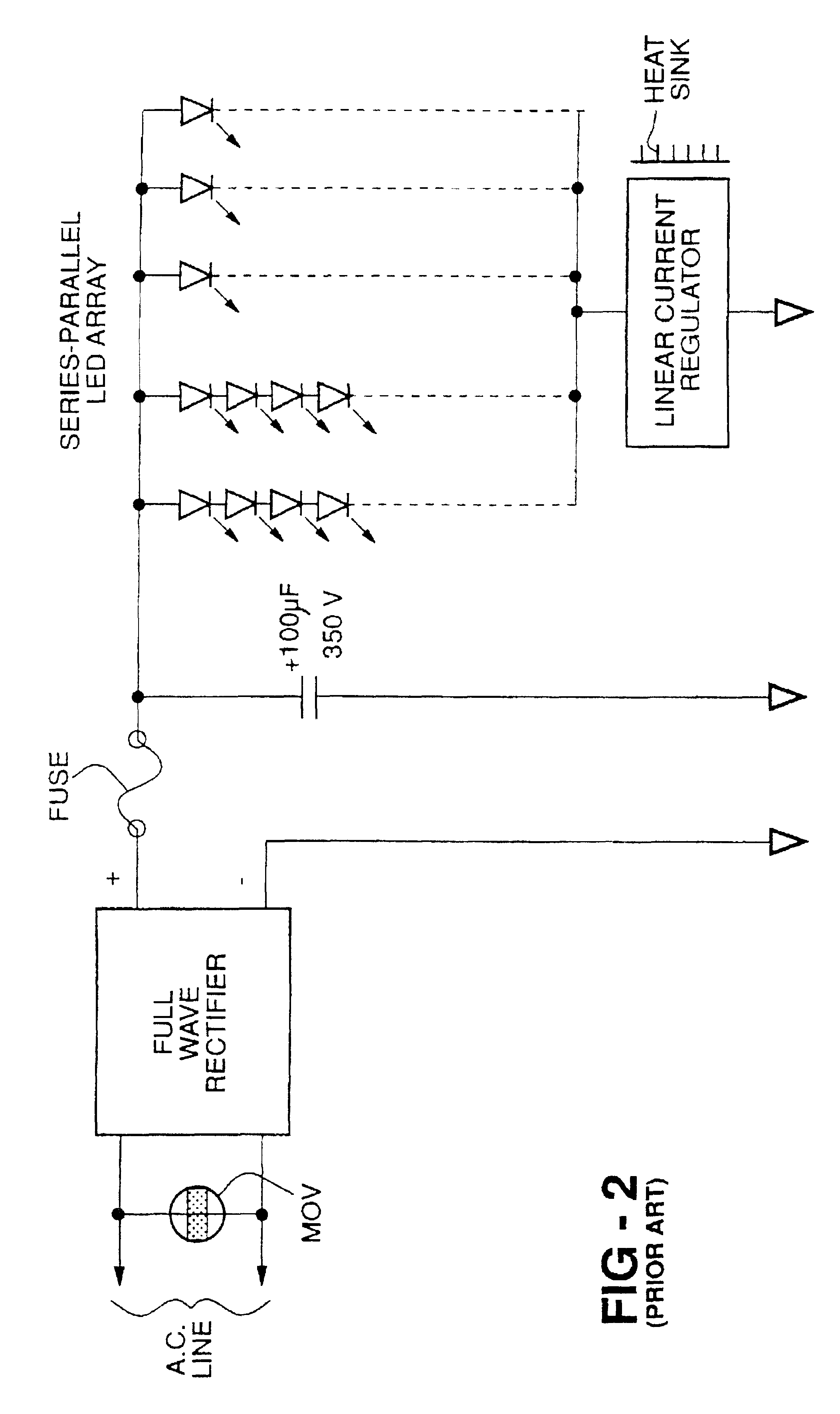
[0031]As noted above, the elementary power supplies that are currently used for powering LED array signals do not meet current standards for efficiency, reliability and performance. The unregulated, resistively ballasted power supply shown in the FIG. 1 does not isolate the LEDs from line voltage variations, and exhibits a poor power factor because of the rectifier and large capacitor. The commercially produced current regulated LED power supply, which is shown in the FIG. 2, does provide much better LED light intensity regulation with input voltage variation. However, the use of a linear, dissipative (heat producing) regulator presents problems. LEDs are thermally sensitive devices which degrade quickly at elevated temperatures. Since most power supplies for LED signals are part of, or are attached to the LED array, heat rise from the linear regulator can be deleterious. Furthermore, the traditional rectifier-capacitor circuit does not produce a satisfactory power factor.

[0032]The ...


PUM


Abstract

An apparatus (10) for supplying regulated voltage d.c. electrical power to an LED array (12) includes a rectifier (32) responsive to a.c. power for generating rectified d.c. power and a power factor correcting and voltage regulating buck/boost switchmode converter (38) responsive to the rectified d.c. power for generating regulated voltage d.c. power to illuminate the LED array (12). A battery backup system (62) receives the a.c. power applied to the rectifier (32) for charging a rechargeable battery (66) and sensing an a.c. power failure. A switch-over relay (82) is connected between the battery backup system (62) and the rectifier. Upon sensing a failure of the a.c. power, the battery backup system (62) controls the switch-over relay (82) to connect the battery backup system (62) to the rectifier (32) to provide d.c. power to the switchmode converter (38) to illuminate the LED array (12). A half wave power detector (88) causes the apparatus (10) to reduce regulated d.c. power to dim the LED array (12).

Description

CROSS-REFERENCE TO RELATED APPLICATIONS [0001]This application is the parent of a continuation reissue application filed Mar. 5, 2008, and accorded application Ser. No. 12 / 074,723.<?insert-end id="INS-S-00001" ?>BACKGROUND OF THE INVENTION[0002]The present invention relates generally to an apparatus for generating power to a light emitting diode array and, in particular, to a power supply for operating light emitting diode array traffic signals.[0003]Light emitting diode (LED) arrays are becoming more common in many applications as they are used to replace less efficient incandescent lamps. Status annunciators, message boards, liquid crystal display back lights and traffic signals are common applications for LED arrays. In most of these uses, electrical power is obtained from a.c. mains (120 v.a.c., 60 Hz) and some form of power supply converts the alternating line voltage to d.c., or pulsing d.c., for powering the plurality of LEDs.[0004]LEDs typically exhibit forward voltage...

Claims


Application Information

Patent Timeline
IPC IPC(8): H02M5/42H02J9/06H02M1/00H02M1/42H05B44/00H05B45/50
CPCH02J9/065H02M1/4208H05B33/0848H05B33/0887H05B33/0842Y02B70/126H05B45/14H05B45/50Y02B70/10H05B45/3725H05B45/355H05B45/36H05B45/325Y02B20/30
Inventor HOCHSTEIN, PETER ANTHONY
Owner AGREEMENT & DECLARATION OF TRUST DATED JUNE 1 2009
Why Eureka
Try Eureka