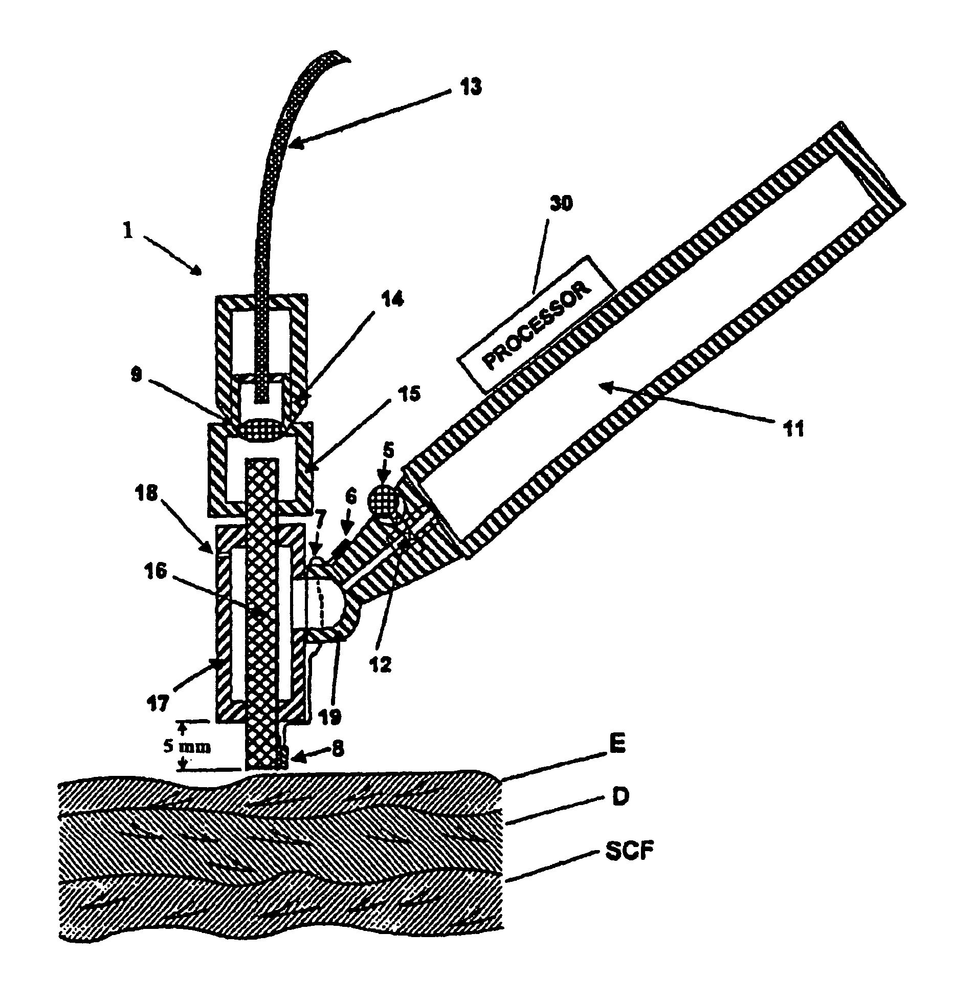
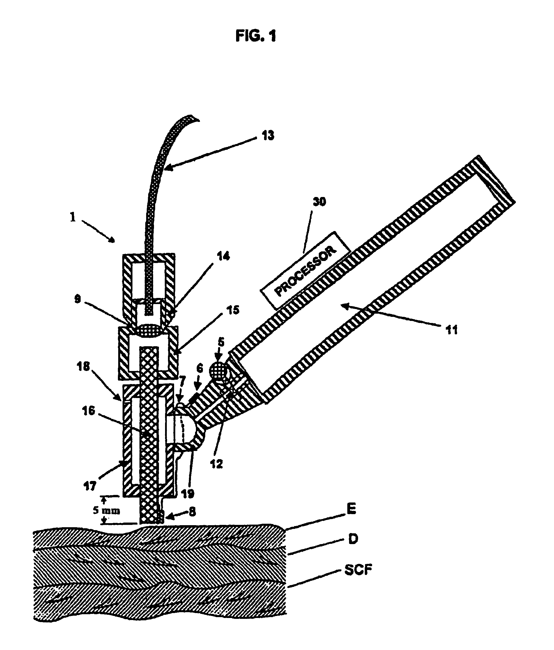
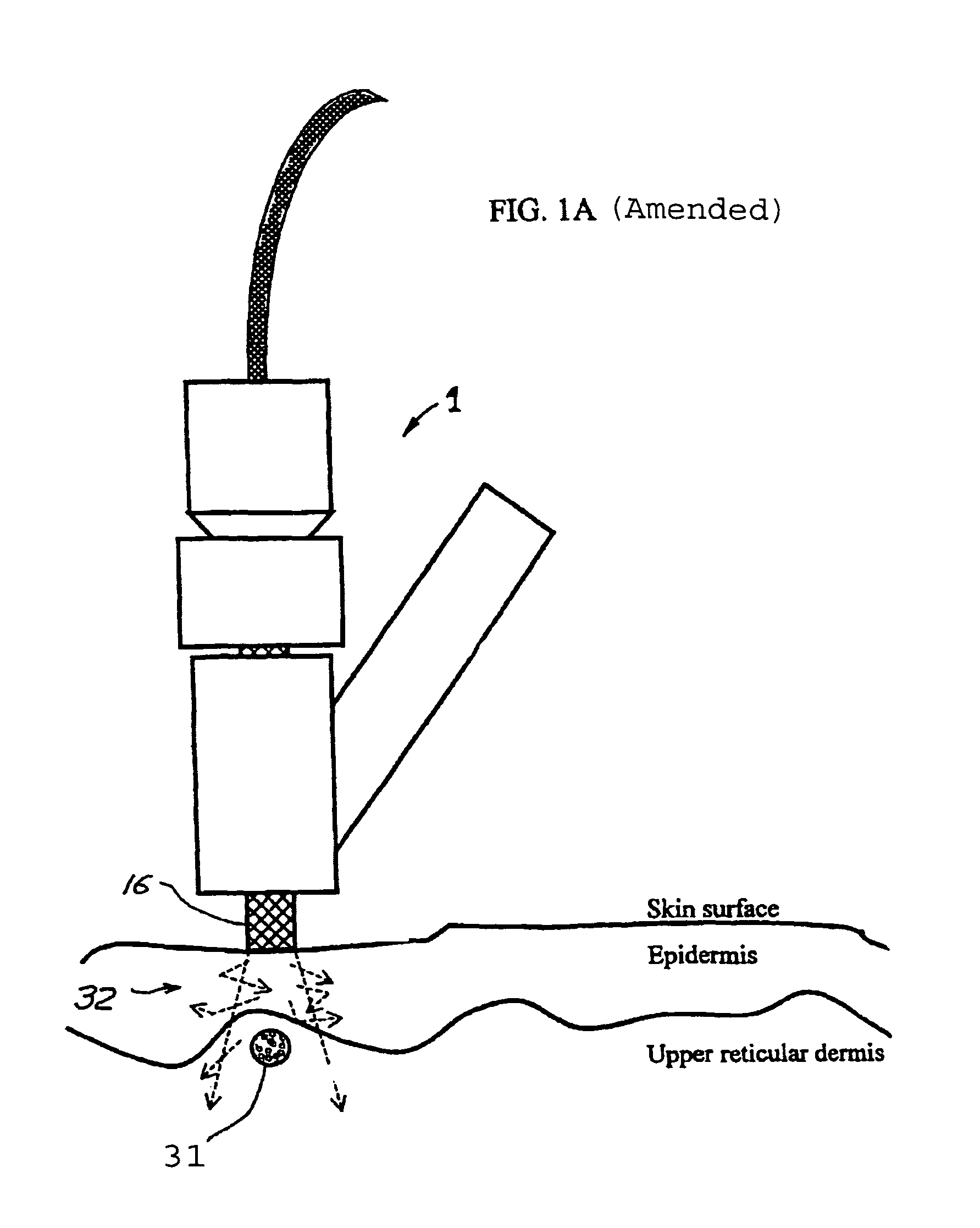
Tissue cooling rod for laser surgery

a technology of laser surgery and cooling rod, which is applied in the field of tissue cooling rod for laser surgery, can solve the problems of affecting the cooling effect of surgical instruments, affecting the treatment effect, and affecting the treatment effect, and achieves the effect of high heat conduction properties

Inactive Publication Date: 2011-08-02
RELIANT TECH INC
View PDF158 Cites 6 Cited by
  • Summary
  • Abstract
  • Description
  • Claims
  • Application Information

AI Technical Summary

Problems solved by technology

Cryogenic spray directly to the skin may reduce a skin temperature below 0 C0° C. but can freeze the skin and cause significant damage to it.
Typical cold contacting windows of the prior art utilize ice water at 0 C0° C. can cool the surface of the skin to as low as about 4 C4° C. But prior art ice water cooled cold contact window devices are inadequate to remove enough heat to prevent unwanted surface tissue damage in many applications.
This method is normally not satisfactory.
The surface gets too cold and the subsurface layers are not sufficiently cooled so that unwanted damage occurs at the surface because the tissue gets too cold from the cryogen and / or unwanted damage occurs in the immediate subsurface layers because the tissue gets too hot from the laser beam.
The techniques do not work well for deeper, larger blood vessels.

Method used


Image

  • Tissue cooling rod for laser surgery
  • Tissue cooling rod for laser surgery
  • Tissue cooling rod for laser surgery

Examples


second embodiment

[0044]A second embodiment involves the use of a cryogenically cooled diamond cooling element as shown in FIGS. 5A and 5B. The device consists of copper holder 24, which has a cryogenic container 21. Synthetic diamond cooling element 23 is in the shape of a flattened cylinder and contains a circular groove through which cryogenic mist flows. The mist exits at the exit port 26.

[0045]The flattened diamond rod is transparent to the laser beam. It is applied to the part of the cleaned skin to be treated. The nozzle valve opens the shutter and the cryogenic spray flows to the chamber around this window. When the window is cold the “ready” light will be switched-on. The energy delivery procedure can be started. This device is good for the large area irradiation such as subsurface tumor interstitial thermotherapy with a high frequency electromagnetic radiation.

PATERNED COOLING ELEMENT FOR MASKING PORTIONS OF TISSUE

third embodiment

[0046]A third embodiment for practicing this invention is to use a patterned rod to the surface of the skin in order to have damaged and healthy areas under the skin surface. FIGS. 3A and 3B show rod 31 with the perpendicular grooves 32 filled with copper stripes 33.

[0047]A laser light is sent through the cooled rod to the surface of the skin does not penetrate through the copper stripes. But the contacting surface of the rod has an almost uniform temperature distribution. It means that the surface of the skin is cooled uniformly. But under skin damage is not uniform having irradiated and not irradiated healthy spots. The reason to have these healthy untouched spots around the damaged tissue is to use the capacity of healthy spot tissue and cells for the fast immune response and wound healing process.


PUM

PropertyMeasurementUnit
temperatureaaaaaaaaaa
depthaaaaaaaaaa
depthaaaaaaaaaa

Abstract

A laser treatment device and process with controlled cooling. The device contains a cooling element with high heat conduction properties, which is transparent to the laser beam. A surface of the cooling element is held in contact with the tissue being treated while at least one other surface of the cooling element is cooled by the evaporation of a cryogenic fluid. The cooling is coordinated with the application of the laser beam so as to control the temperatures of all affected layers of tissues. In a preferred embodiment useful for removal of wrinkles and spider veins, the cooling element is a sapphire plate. A cryogenic spray cools the top surface of the plate and the bottom surface of the plate is in contact with the skin. In preferred embodiments the wavelength of the laser beam is chosen so that absorption in targeted tissue is low enough so that substantial absorption occurs throughout the targeted tissue. In a preferred embodiment for treating large spider veins with diameters in the range of 1.5 mm, Applicants use an Er:Glass laser with a wavelength of 1.54 microns.

Description

[0001]This application is a continuation-in-part application of U.S. Ser. No. 09 / 174,065 filed Oct. 16, 1998 U.S. Pat. No. 6,059,820. This invention relates to devices and methods for laser treatment and in particular to laser treatment with surface cooling.BACKGROUND OF THE INVENTION[0002]1. Prior Art Skin Cooling[0003]The principal methods presently used for skin cooling before or during the laser treatment involve the use of a cold contacting window or cryogenic spray device. Cryogenic spray directly to the skin may reduce a skin temperature below 0 C0° C. but can freeze the skin and cause significant damage to it. Typical cold contacting windows of the prior art utilize ice water at 0 C0° C. can cool the surface of the skin to as low as about 4 C4° C. But prior art ice water cooled cold contact window devices are inadequate to remove enough heat to prevent unwanted surface tissue damage in many applications.[0004]Three prior art techniques are described in the following United S...

Claims


Application Information

Patent Timeline
Patent Type & Authority Patents(United States)
IPC IPC(8): A61B18/18A61B17/00A61B18/00A61B18/02A61B18/20A61B18/22A61B19/00
CPCA61B18/0218A61B18/20A61B18/203A61B18/22A61B2017/00092A61B2017/00734A61B2018/00023A61B2018/00029A61B2018/00452A61B2018/00458A61B2018/0047A61B2018/00636A61B2090/065A61B18/02A61B18/04A61B2018/0231A61B2018/0237A61N2005/002A61N2005/0644
Inventor TANKOVICH, NIKOLAIBARANOV, EUGENE
Owner RELIANT TECH INC
Why Eureka
Try Eureka