
System and method for identifying co-channel interference in a radio network

Inactive Publication Date: 2012-12-25
PCTEL INC
View PDF31 Cites 3 Cited by
  • Summary
  • Abstract
  • Description
  • Claims
  • Application Information

AI Technical Summary

Benefits of technology

[0018]The present invention overcomes the limitations in the prior art by providing systems and methods for identifying co-channel interference in a radio network. In an exemplary method according to the present invention, a first stream of transmission data having a first received signal frequency at a first reception location for a first period of time is received. Further, the first signal frequency of the fir

Problems solved by technology

With the popularity of the service and the limited number of channels available for a given area, the quality of service was not acceptable—especially in the law enforcement and emergency service sectors.
Although the technology utilized in each of these systems can be quite varied, a common problem that arises is the optimization and layout of the cellular network.
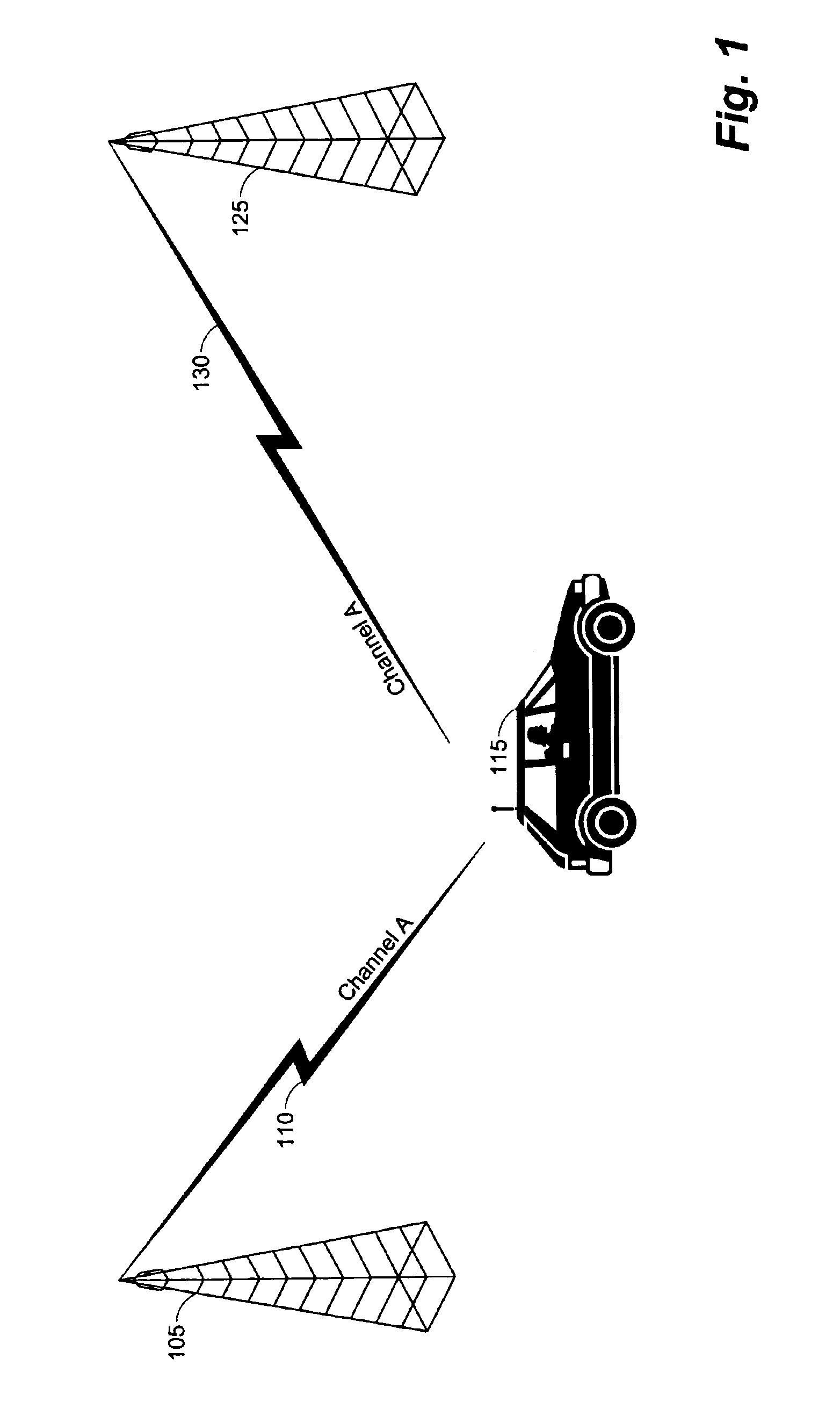
However, reusing cellular channels without having enough geographic separation may result in co-channel interference.
However, once you step away from the chalk board and enter the real world, one that is plagued by buildings, foliage, humidity, uneven terrain, and a host of other parameters, the chalk board calculations don't always provide optimum performance of the cellular telephony system.
It would be exceedingly difficult to attempt to optimize the layout of a cellular system based on each of the possible parameters that effect its operation on paper.
However, this can also be a tremendous task depending on the size of the cellular system, the terrain, and the resources available to the system operator.
A problem associated with signal measurements taken in the field is distinguishing between valid channels and interfering channels.
If the source of a signal cannot be identified (i.e., the transmitting cell tower) then the determination of co-channel interference cannot be accomplished.
This type of system is very prone to error.
While this is marginally acceptable for a non-operating network, it is completely unacceptable for a system that is currently in operation.
Thus, although this technique may result in providing some performance enhancements to the cellular system, the improvements are uncertain, unverified, and inaccurate.
Furthermore, it is generally accepted that propagation prediction algorithms, which have existed since before the advent of cellular telephone, are not very accurate.
This inaccuracy manifests itself in form of poor quality, caused by interference, and sub optimal capacity, caused by excessively restrictive reuse used as hedge against the known prediction inaccuracies.
Until now there has not been hardware capable of making measurements comprehensive enough to replace the predictive models.
Although these measurements work from an engineering point of view, the disruption to the network exceeds the benefit of implementation.
Because the propagation model method of measurement is not practical, some GSM operators have performed signal level measurement testing with hardware that is designed to decode the Base Station Identity Code (BSIC) in GSM.
While this does provide some useful location based information it tells the operator very little about the potential of the network because these receivers cannot distinguish signals in the presence of even a little interference.
First it requires a long time and many changes of frequency plan to build up a usable network map.
Second even though this procedure may improve frequency planning, it does not geographically locate the interference and thus gives no specific information on how to solve or optimize areas with poor performance.

Method used


Image

  • System and method for identifying co-channel interference in a radio network
  • System and method for identifying co-channel interference in a radio network
  • System and method for identifying co-channel interference in a radio network

Examples


Embodiment Construction

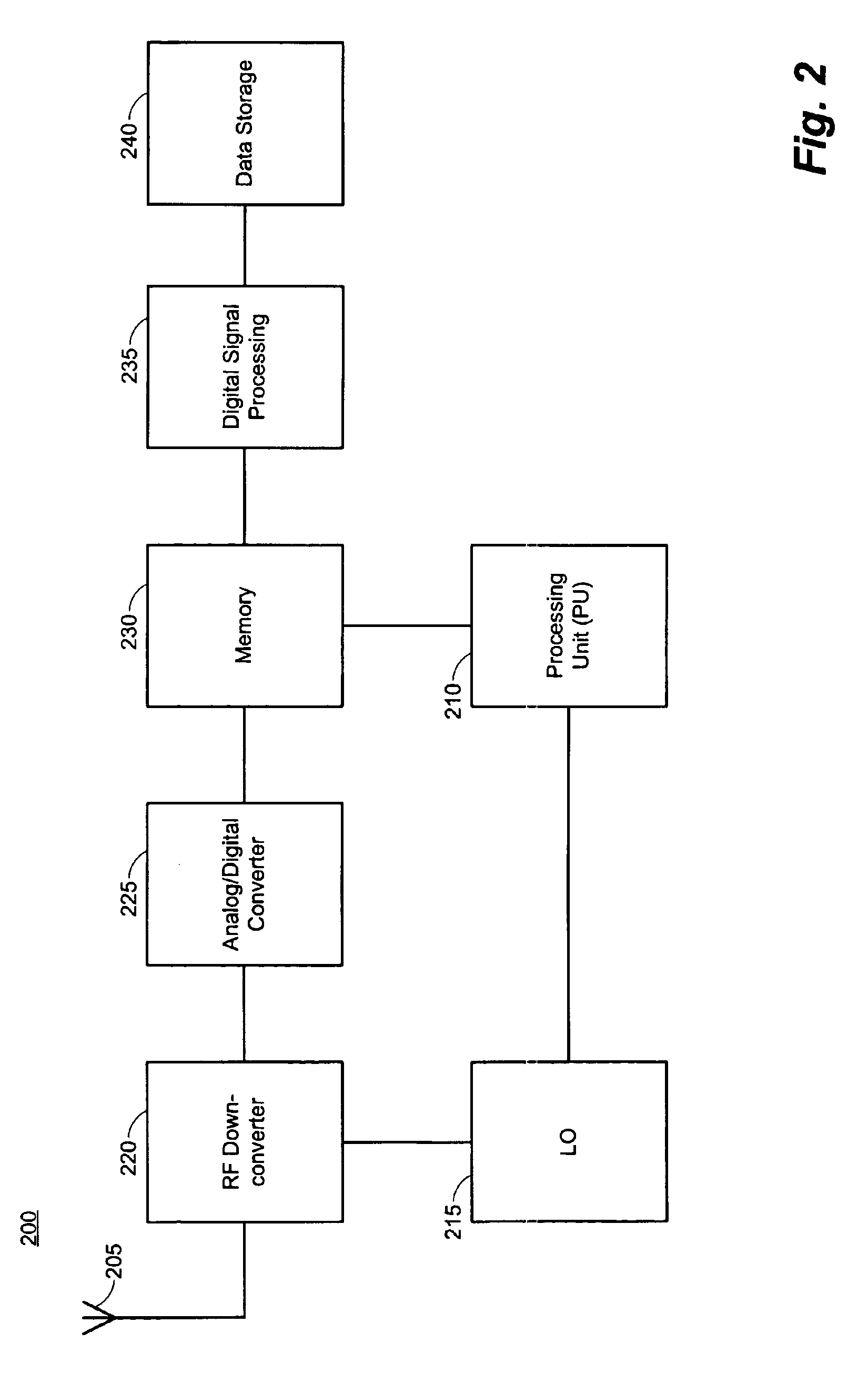
[0035]One aspect of the present invention is a wireless communication test set (WCTS) that is capable of receiving and processing signals over a wide frequency tuning range, as well as for a variety of cellular air interface protocols. Advantageously, this aspect of the present invention improves the ability to receive signals within a cell and analyze the signal for co-channel interference.

[0036]Now turning to the figures where like numbers refer to like elements throughout the several views, various embodiments and aspects of the present invention will be described in more detail. Although the present invention may be applied within a variety of cellular systems having varying technology, the present invention will by primarily described as operating within a GSM cellular network. Any variants that are necessary to utilize the present invention within a different cellular network are also described.

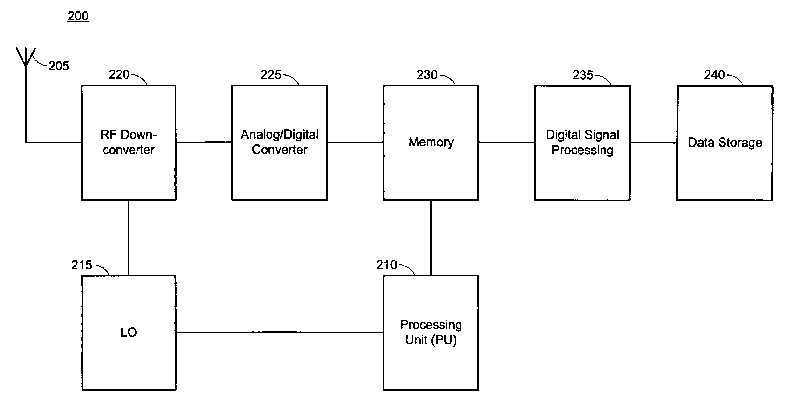
[0037]FIG. 1 is a system diagram illustrating co-channel interference within a cell...


PUM


Abstract

The present invention is directed toward a system and method for identifying co-channel interference in a radio network. In an exemplary method according to the present invention, a first stream of transmission data having a first received signal frequency at a first reception location for a first period of time is received. Further, the first signal frequency of the first stream of transmission data is identified. Then the transmission data is correlated against a signal template to identify a first FCCH burst frame. Then, first FCCH time data corresponding to the first FCCH burst frame is identified and the signal frequency of the first stream of transmission data and the first FCCH time data is compared to a reference file to determine one or more probable transmission cells.

Description

CROSS REFERENCE TO RELATED APPLICATION AND CLAIM OF BENEFIT[0001]This application is based on and claims the priority date of U.S. Provisional Application Ser. No. 60 / 421,397, entitled “SYSTEM AND METHOD FOR IDENTIFYING CO-CHANNEL INTERFERENCE INA RADIO NETWORK”, filed on Oct. 25, 2002, which is incorporated by reference in its entirety as if fully set forth herein.This application claims priority under 35 U.S.C. §119(e) to U.S. Provisional Application Ser. No. 60 / 421,397, entitled “SYSTEM AND METHOD FOR IDENTIFYING CO-CHANNEL INTERFERENCE IN A RADIO NETWORK”, filed on Oct. 25, 2002, which is incorporated by reference in its entirety as if fully set forth herein, and is a Continuation-in-Part of and claims priority under 35 U.S.C §120 to U.S. patent application Ser. No. 09 / 638,921, entitled “RADIO NETWORK TEST ANALYSIS SYSTEM”, filed Aug. 15, 2000.TECHNICAL FIELD [0002]The present invention relates to the field of telecommunication network design and analysis, and in particular, th...

Claims


Application Information

Patent Timeline
IPC IPC(8): H04W4/00
CPCH04W24/00
Inventor SANDERS, ALAN DAVIDLEWARS, PERRY SIMON LINDERDAVE, DHAVAL
Owner PCTEL INC
Learn More