

Separation method of hydrocarbon reaction oil gas
A technology for reacting oil and gas and separating methods, which is applied in the directions of distillation purification/separation, fractionation, hydrocarbon cracking and hydrocarbon production, etc. It can solve the problems that catalyst particles are easy to block the packing pores, it is difficult to meet the separation requirements, and the reaction oil and gas temperature is high, so as to save replacement. Thermal equipment, prolonging the residence time, improving the effect of heat transfer
- Summary
- Abstract
- Description
- Claims
- Application Information
AI Technical Summary
Problems solved by technology
Method used
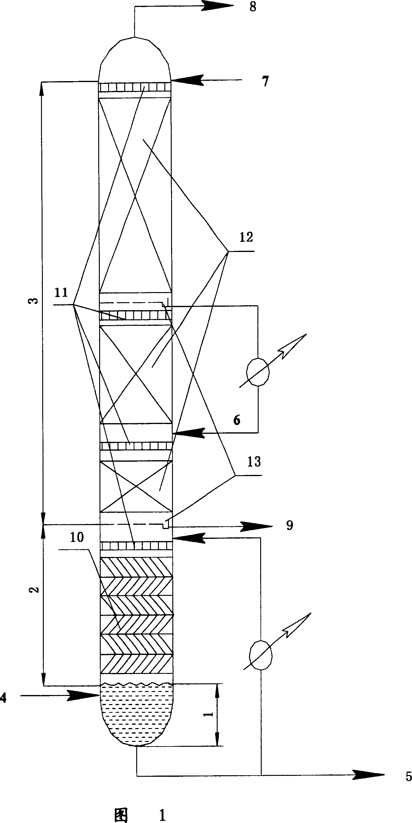
Image

Examples
Embodiment 1
[0042] This embodiment illustrates: the implementation effect of the method provided by the present invention.
[0043] The composition of the reaction oil gas and heavy raw materials used in the test process is shown in Table 1. The main operating conditions of the cold-exchange pre-separation tower are as follows: the top temperature of the cold-exchange pre-separation tower is 223 ° C, the bottom temperature is 452 ° C, and the top The pressure is 1.7 bar and the bottom pressure is 1.9 bar. The separation effect of cold exchange is shown in Table 2. It can be seen from Table 2 that the hydrocarbon mixture rich in light olefins can obtain ideal cooling and separation effects by adopting the method provided by the present invention.
[0044] Table 1
[0045] logistics
[0046] butane
[0047] Distillation range 574°C
[0048] Table 2
[0049] logistics
[0050] Distillation range 156°C
Embodiment 2
[0056] The composition of the reaction oil gas and heavy raw materials used in this embodiment is the same as that of Example 1, and the main operating conditions of the cold-exchange pre-separation tower are as follows: the temperature at the top of the cold-exchange pre-separation tower is 95.6 ° C, and the temperature at the bottom of the tower is 347 ° C. The pressure at the top of the tower is 200KPa, and the pressure at the bottom of the tower is 201KPa. The separation effect of cold exchange is shown in Table 4. It can be seen from Table 4 that the cooling separation of petroleum hydrocarbons rich in low-carbon olefins can be effectively realized by adopting the method provided by the present invention.
[0057] Table 4
[0058] logistics
[0059] Anti-butene
PUM
 Abstract
Description
Claims
Application Information