Air cooled water composite cooling tower

A cooling tower and composite technology, which is applied in the field of air-cooled and cold-water composite cooling towers, can solve the problems of low cooling efficiency, high cost of air coolers, and small specific heat

Inactive Publication Date: 2008-08-20
BEIJING HIKEEN TECH +1
View PDF5 Cites 5 Cited by
  • Summary
  • Abstract
  • Description
  • Claims
  • Application Information

AI Technical Summary

Problems solved by technology

Due to the high dry bulb temperature of the air, small specific heat, limited heat absorption capacity, ...

Method used


Image

  • Air cooled water composite cooling tower
  • Air cooled water composite cooling tower
  • Air cooled water composite cooling tower

Examples


Embodiment Construction

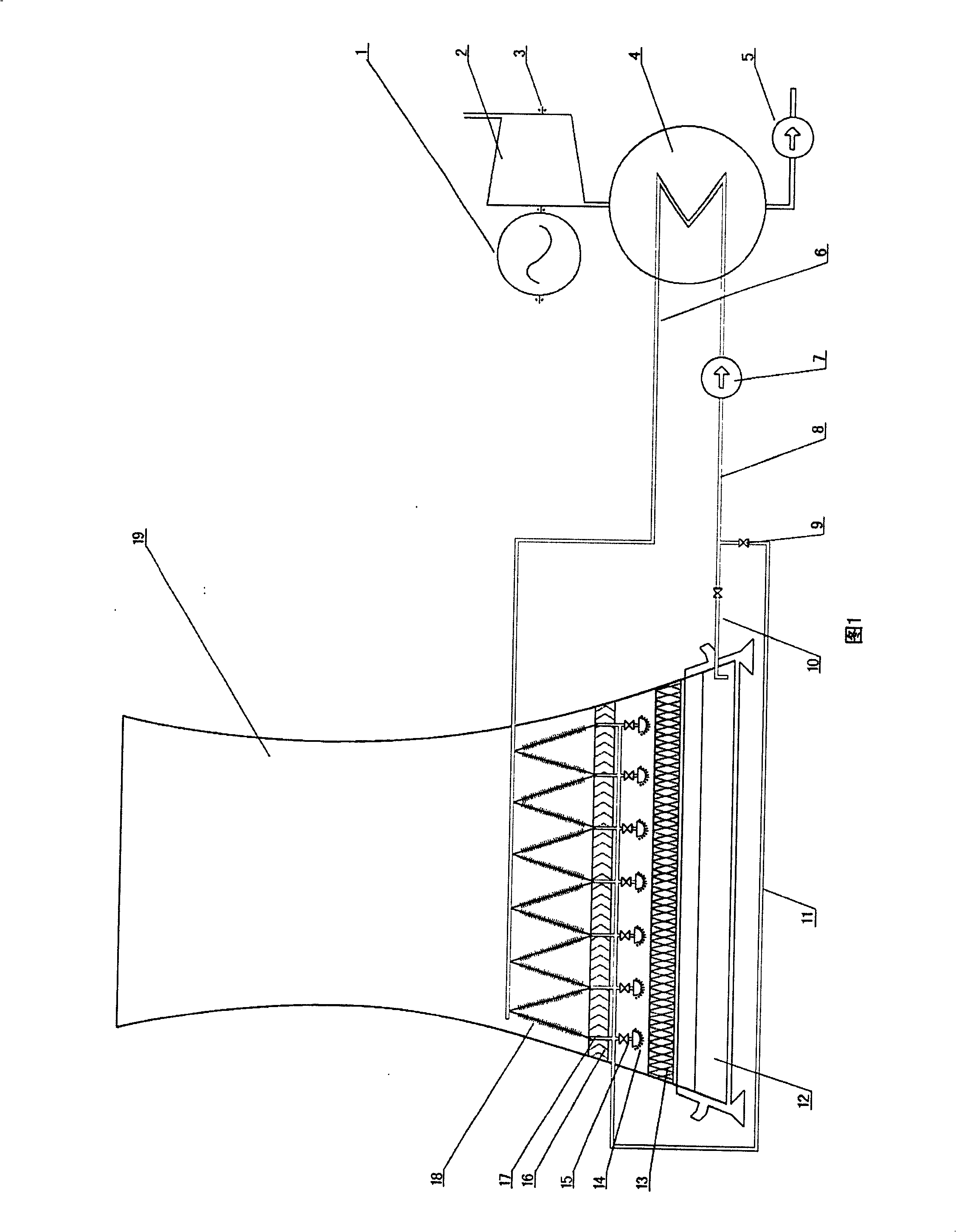
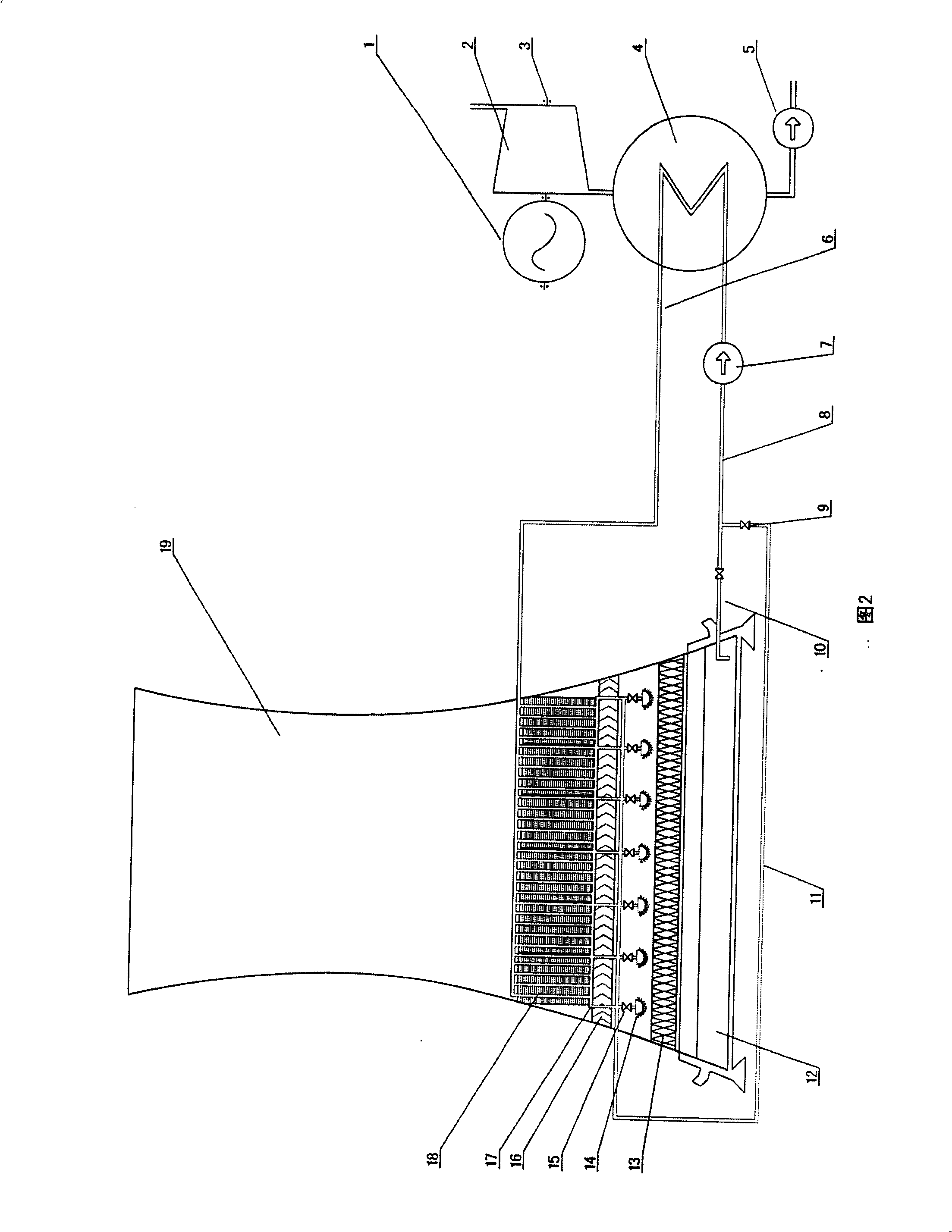
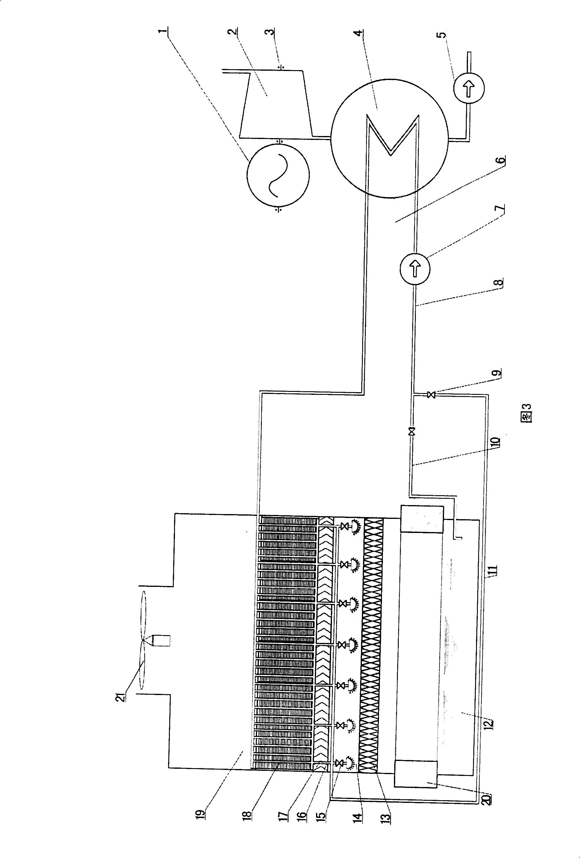
[0016] As shown in Figure 1: on the air cooler bracket 17 arranged in the wind direction under the honeycomb wave water distribution cooling layer 13 and the water distributor 14 in the cooling tower fan duct 19, an air cooler 18 arranged in a herringbone shape is installed. The mounting bracket 17 of the arranged air cooler 18 is fixed on the load-bearing support body of the cooling tower. The hot circulating water to be cooled enters the cooling tower air duct 19 through the hot circulating water delivery main pipe 6, and is respectively connected with the water inlets on the air cooler 18 arranged in a herringbone shape, and is uniformly distributed through the water distribution pipes with equal flow paths and equal pressures. The water is distributed in the air cooler 18 arranged in a herringbone shape. The hot water cooled by the air cooler is collected through the water collection pipe 11 at the end of the air cooler, and the water is distributed in the honeycomb by the ...


PUM


Abstract

Heat exchanger packs having a first set of passageways for receiving a stream of ambient air and a second set of passageways for receiving a stream of warm water laden air is disclosed. The first set of passageways and second set of passageways being separate and permitting the warm water laden air stream to be cooled by the stream of ambient air so that water can condense out of the warm water laden air stream. Cooling tower configurations including the heat exchanger pack are disclosed for achieving effluent plume abatement, and capture of a portion of the effluent for replacement back into the cooling tower reservoir or as a source of purified water.

Description

technical field [0001] The invention relates to an air-cooled and cold-water composite cooling tower, which belongs to the application field of cooling devices. Background technique [0002] At present, known cooling towers are two main forms of cold water type and air cooling type. These two cooling towers have natural draft cooling towers and mechanical draft cooling towers. Since the cooling tower is mainly affected by the wet bulb temperature of the air, it relies on the evaporation and conduction of water to dissipate heat, so its consumption of water is very large. The air cooling tower uses conduction to make the air absorb heat to achieve heat dissipation, which is mainly affected by the dry bulb temperature of the air. Due to the high dry bulb temperature of the air, small specific heat, limited heat absorption capacity, and low cooling efficiency, the air cooler needs to have a large surface area, making the air cooler expensive. Contents of the invention [0...

Claims


Application Information

Patent Timeline
IPC IPC(8): F28C1/00F28C1/14
CPCF28C1/14F28B9/06Y02B30/70
Inventor 徐宝安
Owner BEIJING HIKEEN TECH
Why Eureka
Try Eureka