Photoelectric converting apparatus
A technology of photoelectric conversion and photoelectric conversion elements, applied in the direction of TV, electrical components, color TV, etc., can solve the problems of difficult to form high-sensitivity photoelectric conversion equipment, output voltage loss, high power consumption, etc., to reduce the influence of resistance , low power consumption, low heat effect
- Summary
- Abstract
- Description
- Claims
- Application Information
AI Technical Summary
Problems solved by technology
Method used
Image

Examples
no. 1 example
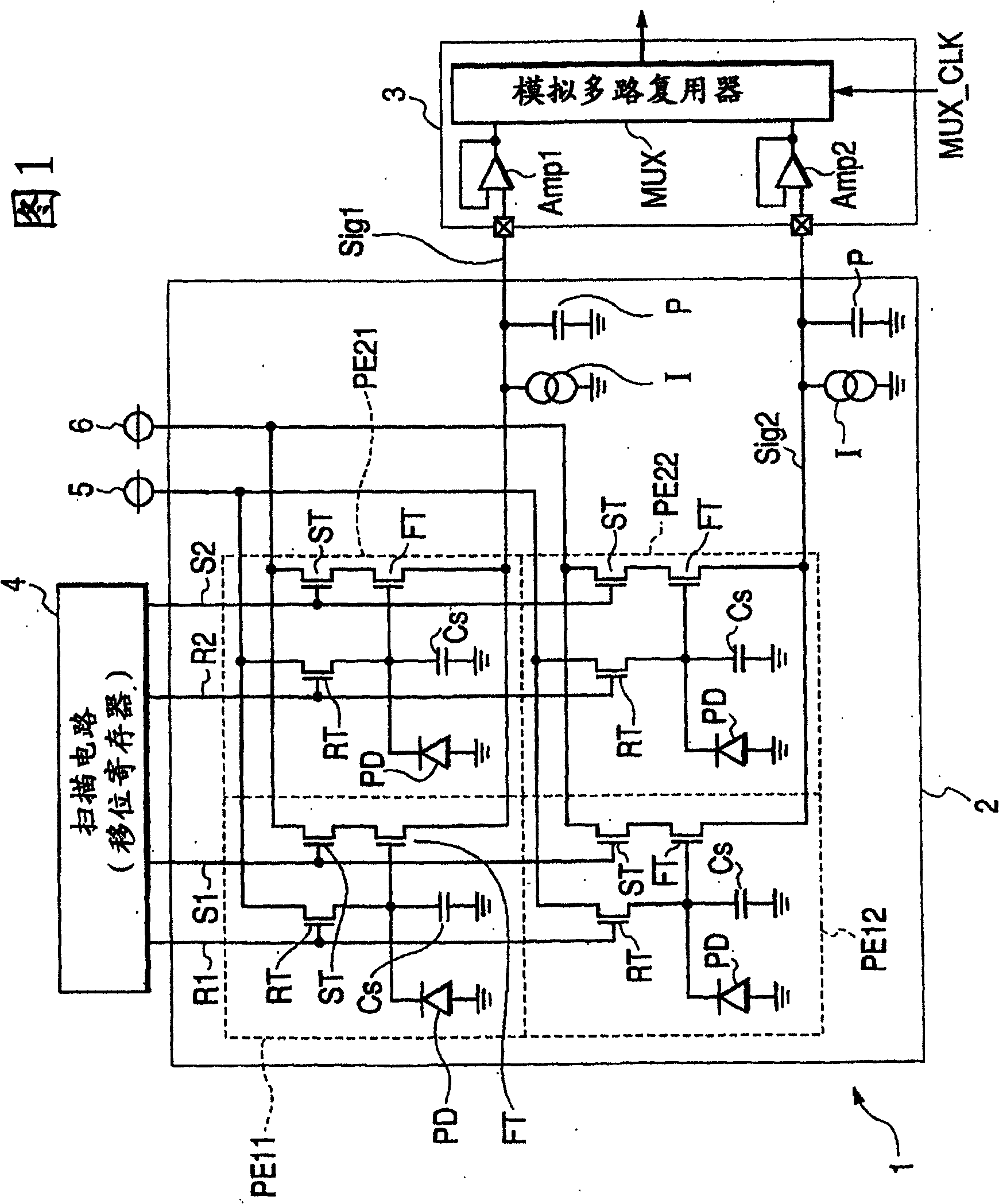
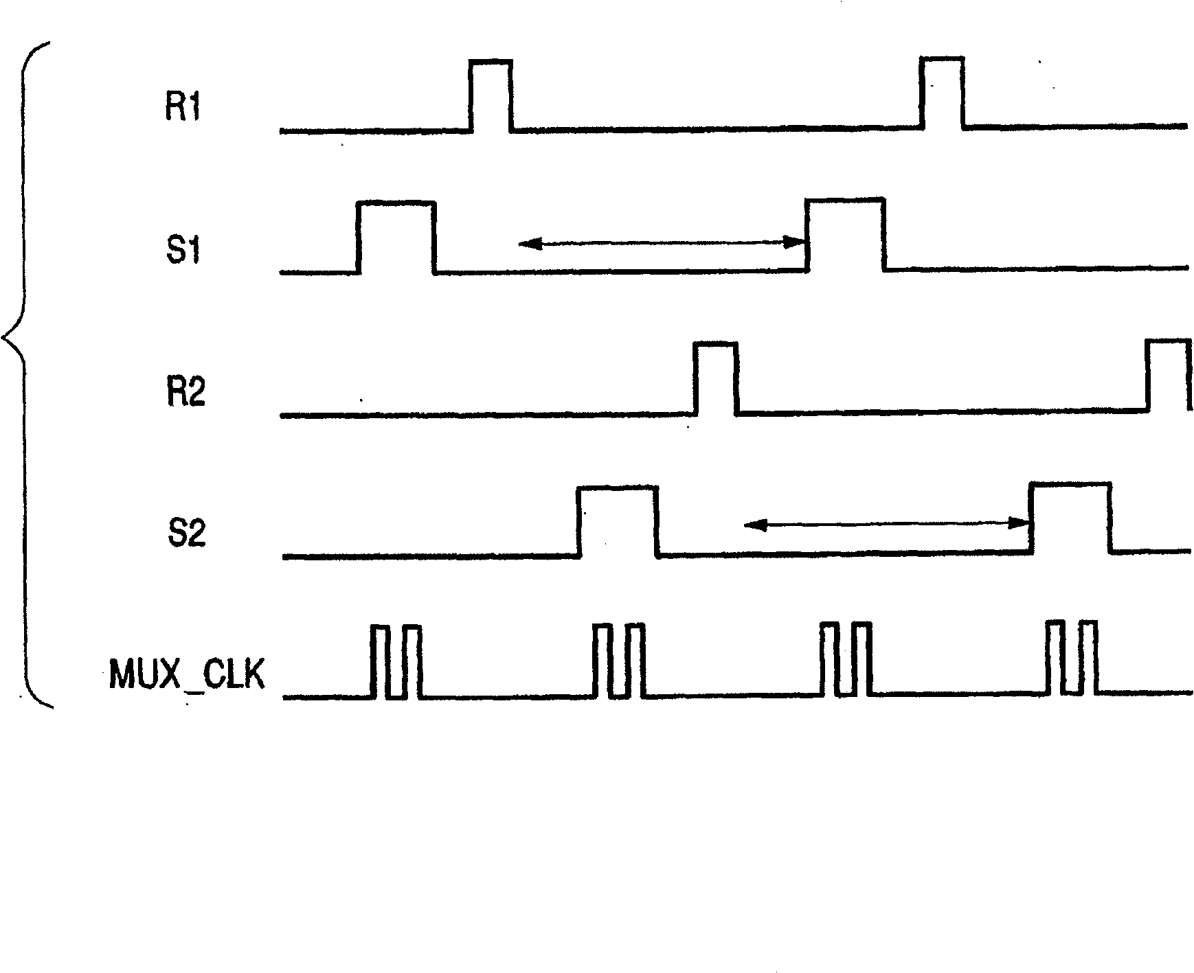
[0040] First, a first embodiment of the present invention will be described. FIG. 1 is a circuit diagram showing a circuit configuration of a photoelectric conversion device constituting a first embodiment of the present invention, particularly an X-ray image pickup device.
[0041]In this embodiment, the sensor array 1 is formed on the glass substrate 2 by arranging four pixels PE11, PE12, PE21, and PE22 in two rows and two columns, but the number of pixels constituting the sensor array 1 is not limited to such example. Each pixel has a photoelectric conversion element PD composed of a PIN photodiode formed of amorphous silicon, and a storage capacitor Cs that accumulates signal charges generated by the photoelectric conversion element PD. The photoelectric conversion element PD and the storage capacitor Cs are grounded at one end thereof and interconnected at the other end thereof. Each pixel also has a reset MOS transistor RT, a selection MOS transistor ST, and a source f...
no. 2 example
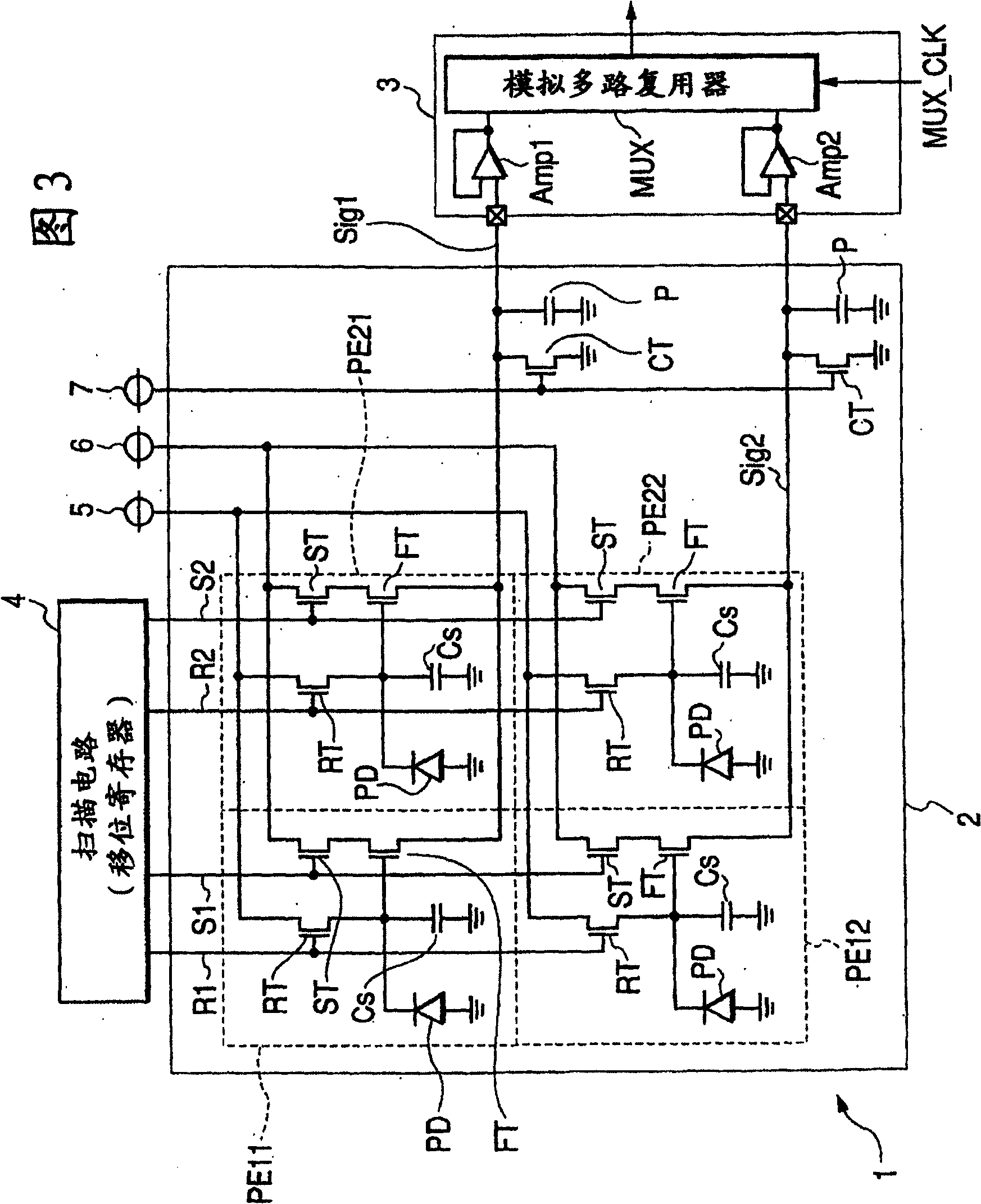
[0053] Next, a second embodiment of the present invention will be described. 3 is a circuit diagram of a circuit configuration of a photoelectric conversion device, particularly an X-ray image pickup device, constituting a second embodiment of the present invention. In the second embodiment, instead of the constant current source I employed in the first embodiment, a thin film transistor (TFT) CT formed of amorphous silicon is provided. The gate of the thin film transistor CT receives a voltage from a power source 7 for a constant current source. Such a structure can be produced by a simple manufacturing process, because a constant current source can be formed simultaneously with other transistors (reset, select, and source follower) by film formation. Thin film transistors respectively used for reset, selection, source follower, and constant current source may have the same laminated film thickness or different film thicknesses. They may also have a common doping state (n-t...
no. 3 example
[0059] A third embodiment of the present invention will be described below. 5 is a circuit diagram of a circuit configuration of a photoelectric conversion device, particularly an X-ray image pickup device, constituting a third embodiment of the present invention. Contrary to the second embodiment in which the thin film transistor CT constituting the constant current source is placed between the pixel and the readout circuit 3, in the third embodiment, on the common signal line, the thin film transistor CT is located at a distance from the pixel compared with the pixel. The readout circuit 3 is farther away. In other words, the pixel is arranged between the thin film transistor CT and the readout circuit 3 .
[0060] The advantage of arranging the constant current source at a distance from the readout circuit will now be described with reference to FIGS. 15, 16 and 17. FIG. FIG. 15 shows a structure in which, for each signal line, a constant current source is spaced apart fr...
PUM
 Abstract
Description
Claims
Application Information
 - R&D
- Intellectual Property
- Life Sciences
- Materials
- Tech Scout
- Unparalleled Data Quality
- Higher Quality Content
- 60% Fewer Hallucinations
Browse by: Latest US Patents, China's latest patents, Technical Efficacy Thesaurus, Application Domain, Technology Topic, Popular Technical Reports.
© 2025 PatSnap. All rights reserved.Legal|Privacy policy|Modern Slavery Act Transparency Statement|Sitemap|About US| Contact US: help@patsnap.com