
T-shaped beam parallel plate micromechanical variable capacitor and manufacturing process thereof

A technology of variable capacitance and T-shaped beams, which is applied in the direction of variable capacitors, capacitors that change capacitance in a non-mechanical way, capacitors, etc., can solve the incompatibility of mainstream integrated circuit processes, poor repeatability and reliability, and high production costs. problems, to achieve the effects of improved repeatability, reliability, convenience and effective control, and reduced production costs

Inactive Publication Date: 2009-02-25
SOUTHEAST UNIV
View PDF6 Cites 0 Cited by
  • Summary
  • Abstract
  • Description
  • Claims
  • Application Information

AI Technical Summary

Problems solved by technology

The application of the T-beam parallel plate MEMS variable capacitance structure to the mass production of integrated circuits has a series of obstacles such as incompatibility with mainstream processes, poor repeatability and reliability, and high production costs.

Method used


Image

  • T-shaped beam parallel plate micromechanical variable capacitor and manufacturing process thereof
  • T-shaped beam parallel plate micromechanical variable capacitor and manufacturing process thereof
  • T-shaped beam parallel plate micromechanical variable capacitor and manufacturing process thereof

Examples


Embodiment Construction

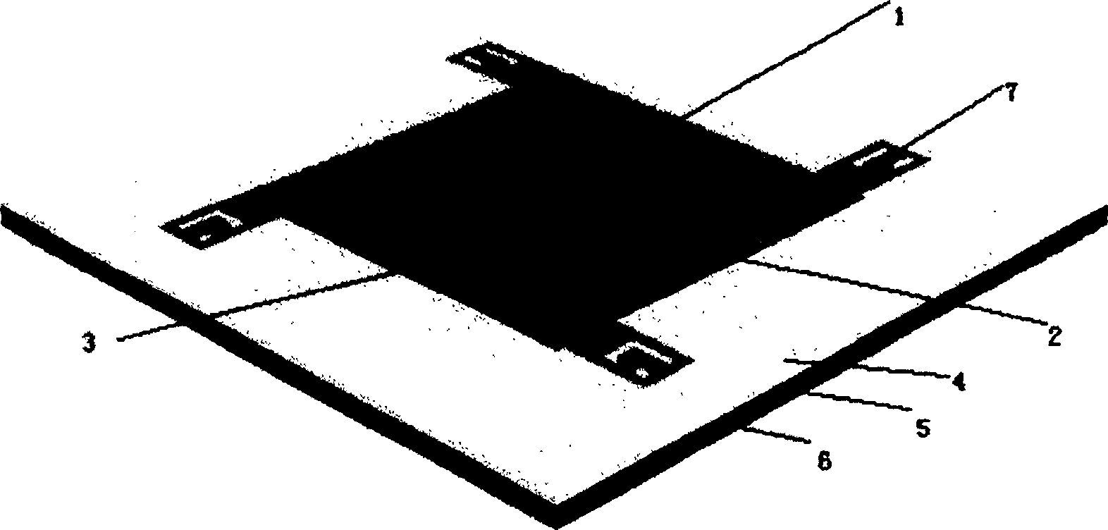
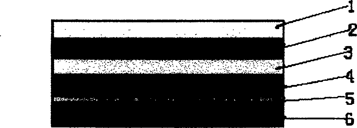
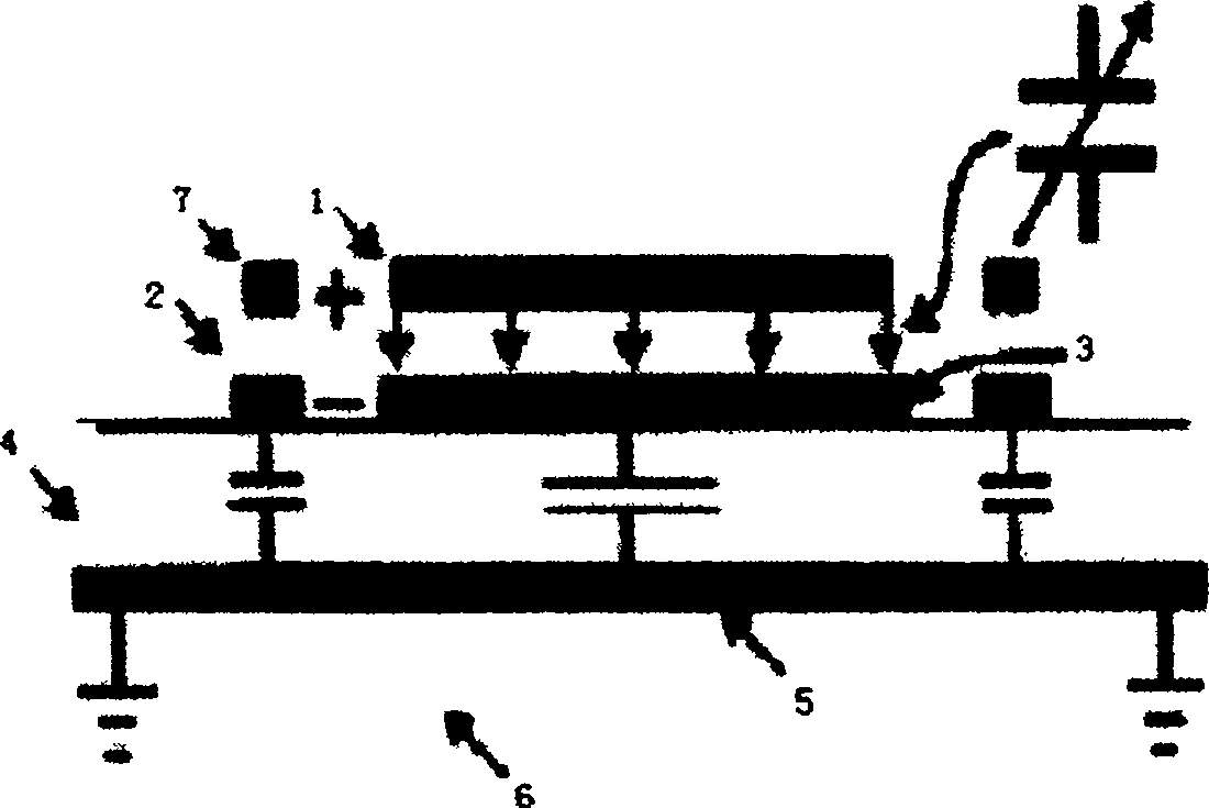
[0031] For the T-beam parallel plate MEMS variable capacitance structure of the present invention, we have proposed a realization method based on CMOS technology. This structure uses the form of voltage change between parallel plates to realize the change of capacitance, and its layered structure is sequential from top to bottom These are: aluminum 1 on the upper plate, dielectric layer 2, aluminum 3 on the lower plate, insulating layer 4, conductive shielding layer 5, and silicon substrate 6; T-beams 7 are arranged symmetrically outside the aluminum 1 on the upper plate. The T-beam 7 is composed of a T-beam connecting arm 7.1 and a T-beam anchoring area 7.2, and a "U"-shaped through-slot 7.3 is opened in the middle of the T-beam connecting arm 7.1, and the T-beam anchoring area 7.2 is located in the " U"-shaped through groove 7.3. An anchor block 7.2.1 is provided at the bottom of the shaped beam anchorage area 7.2.

[0032] We have designed the specific process of T-beam pa...


PUM


Abstract

T-shaped girder clinograph micro-machinery variable capacitance and its production technique make use of the structure of the T-shaped girder and clinograph to realize the micro-machinery variable capacitance, which makes use of the change of the voltage between the two clinographs to realize the change of the capacitance. Its layered structure from the upper to the lower is as follows: upper plank aluminium (1), dielectric layer (2), lower plank aluminium (3), insulating layer (4), electric shielding layer (5) and silicon substrate (6). The T-shaped girder (7) is corresponding to the upper plank aluminium (1). The concrete preduction method is as follows: preparing the substrate, preparing the oxidizing layer, adulterating the p+ polysilicon film on the field oxygen, preparing the insulating medium of SiO2 film, making the lower plate electrode of the capacitance of the first layer interconnecting metallic aluminium, preparing the PSG sacrificial layer, preparing the upper plate electrode, releasing the sacrificial layer and depositing the passive film. The variable capacitance is featured by simple structure and high reliability and its preparation technique is compatible to the main stream of CMOS.

Description

technical field [0001] The invention uses a T-shaped beam and a parallel plate structure to realize a micromechanical variable capacitor, and belongs to the technical field of microelectronic device manufacturing. Background technique [0002] Due to the need for system size miniaturization, high reliability and cost reduction in the field of personal communication and military communication, research on MEMS (micro-mechanical) devices has also been carried out in the field of radio frequency. Many modern radio systems require a high-quality voltage-controlled oscillator (VCO) capable of wide amplitude modulation and low noise over a frequency range of several gigahertz. Tonality is usually provided by a variable capacitor. Since it is difficult to achieve a high quality factor for a variable capacitor integrated on a chip, the variable capacitor is usually implemented with external components. Low noise means that it is necessary to have a circuit with high quality factor...

Claims


Application Information

Patent Timeline
Patent Type & Authority Patents(China)
IPC IPC(8): H01G7/00H01L29/00H01L27/00H01L21/02H01L21/82B81B7/00B81C5/00B81C99/00
Inventor 廖小平李锐
Owner SOUTHEAST UNIV
Learn More