High-frequency clock jitter measuring circuit and calibration method thereof
A technology for measuring circuits and high-frequency clocks, which is applied in the direction of measuring electricity, measuring electrical variables, and frequency measuring devices. It can solve the problem that the clock cannot be used in measuring jitter circuits, achieve fast and efficient delay adjustment, improve flexibility, and use convenient effect
- Summary
- Abstract
- Description
- Claims
- Application Information
AI Technical Summary
Problems solved by technology
Method used
Image
Examples
specific Embodiment 1
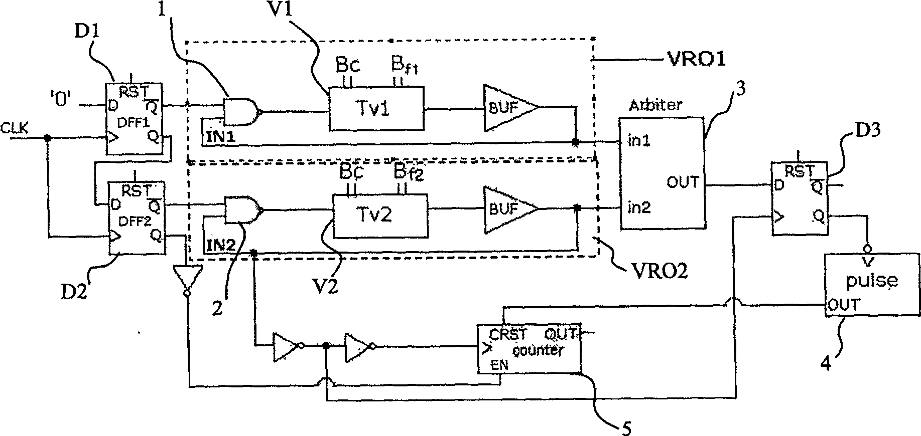
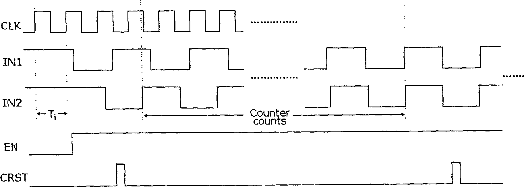
[0054] Specific embodiment one, such as figure 1 Shown is the overall structure diagram of the jitter measurement. The jitter measurement circuit mainly includes: a first oscillation signal generation unit, a second oscillation signal generation unit, a first reset control unit and a first counting unit.
[0055] The first oscillating signal generation unit includes the first D flip-flop D1 and the first ring oscillator VRO1 connected in series, the first ring oscillator VRO1 includes the first NAND gate 1 and the first ring oscillator V1 as the first opening module, the first The input terminal of a D flip-flop D1 inputs a low level, the clock input terminal inputs the measured clock signal CLK, and the first NAND gate 1 responds to the negative output terminal output signal of the first D flip-flop D1 and the first oscillation signal in1 respectively, The output end is coupled to the first ring oscillator V1, and the first ring oscillator V1 generates and outputs a first osc...
specific Embodiment 2
[0068] Embodiment 2. The difference from Embodiment 1 is that the output terminals of the first and second ring oscillators are additionally connected with a buffer drive BUF, in order to reduce the impact of the load circuit on the ring oscillator frequency.
specific Embodiment 3
[0069] Specific Embodiment 3. On the basis of specific embodiments 1 and 2, the ring vibration is improved, and the ring vibration adopts a differential control method. One disadvantage of the original vernier caliper type TDC is that it occupies a relatively large area, and the higher the accuracy, the larger the area.
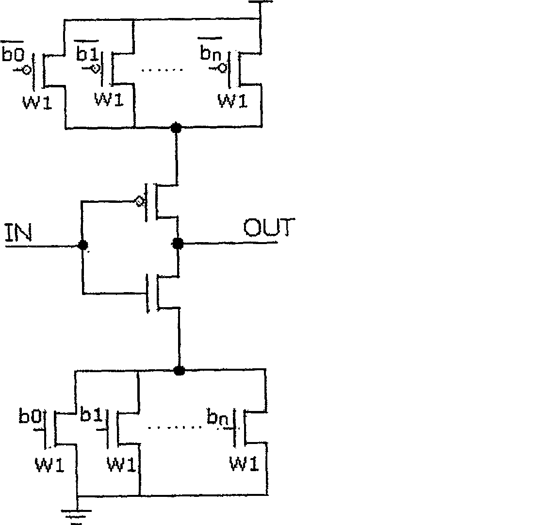
[0070] In this method, the first and second ring oscillators are composed of an odd number of inverter delay units to form a feedback closed loop. In order to make the oscillation frequency variable, the delay amount of the inverter delay unit is designed to be controllable. In order to facilitate The system is compatible with the digital system, and this control adopts the digital control method.
[0071] Traditional inverter delay units such as image 3 As shown, the number of PMOS and NMOS transistors that are turned on is selected through the control word B, so as to control the current when the inverter level jumps, and then control the delay of the inver...
PUM
 Abstract
Description
Claims
Application Information
 - R&D
- Intellectual Property
- Life Sciences
- Materials
- Tech Scout
- Unparalleled Data Quality
- Higher Quality Content
- 60% Fewer Hallucinations
Browse by: Latest US Patents, China's latest patents, Technical Efficacy Thesaurus, Application Domain, Technology Topic, Popular Technical Reports.
© 2025 PatSnap. All rights reserved.Legal|Privacy policy|Modern Slavery Act Transparency Statement|Sitemap|About US| Contact US: help@patsnap.com


