
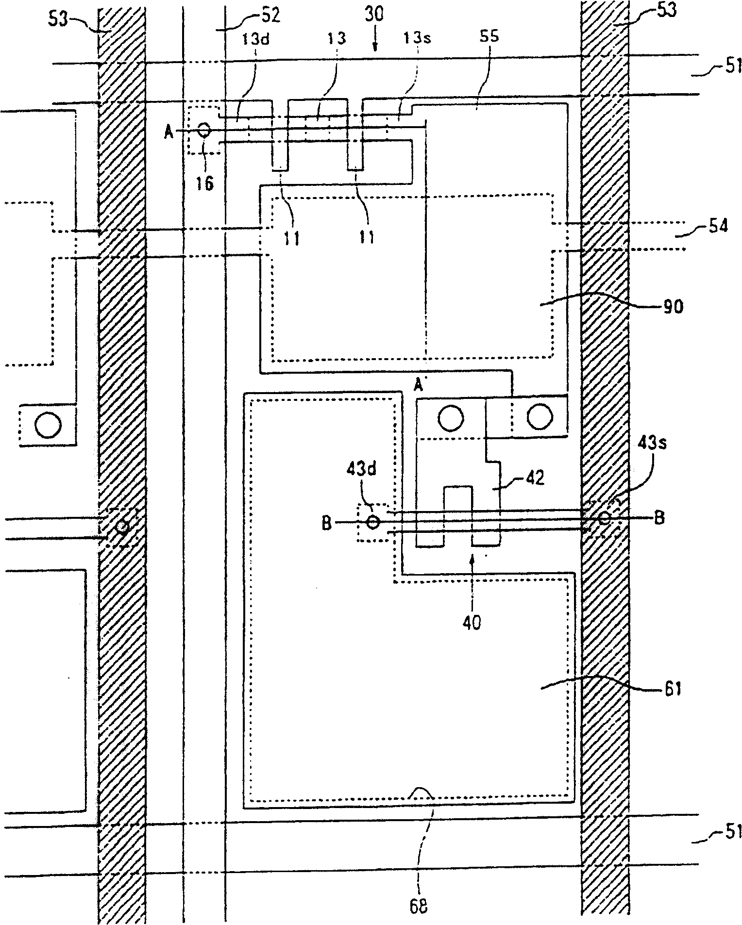
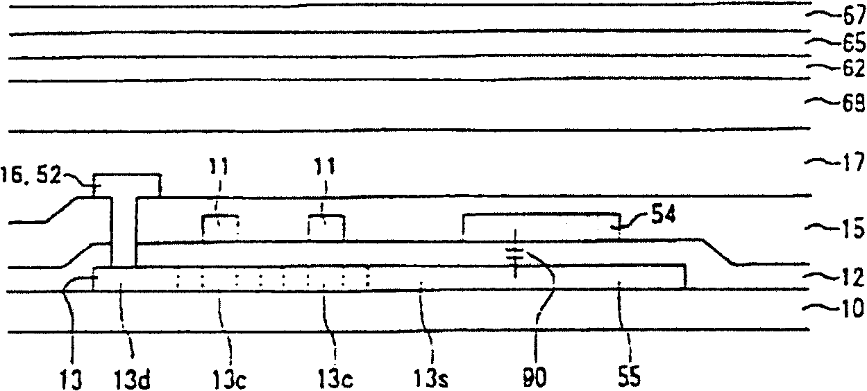
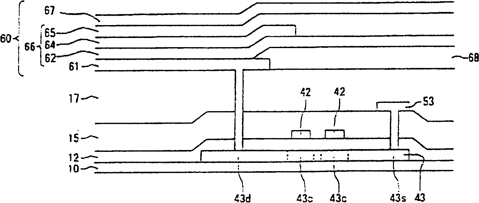
Distributing structure, it mfg. method and optical equipment

A technology for wiring structure and optical equipment, applied in semiconductor/solid-state device manufacturing, light source, electric light source, etc., can solve problems such as increased contact resistance and poor adhesion, and achieves prevention of diffusion, reduction of migration, reduction of The effect of contact resistance

Inactive Publication Date: 2009-07-22
SANYO ELECTRIC CO LTD
View PDF4 Cites 0 Cited by
  • Summary
  • Abstract
  • Description
  • Claims
  • Application Information

AI Technical Summary

Problems solved by technology

[0006] In addition, when wiring made of a low-resistance metal is covered with a protective layer made of a refractory-temperature metal, the degree of adhesion between these layers will deteriorate and the contact resistance will undesirably increase

Method used


Image

  • Distributing structure, it mfg. method and optical equipment
  • Distributing structure, it mfg. method and optical equipment
  • Distributing structure, it mfg. method and optical equipment

Examples


example

[0081] The present invention will be explained with reference to specific examples.

[0082] In the formation of SiO 2 After the film is used as an interlayer insulating film to become a base, a contact hole is formed in the interlayer insulating film. Then, the layered wiring structure is deposited on the interlayer insulating film using a load-lock (LL) type multi-chamber deposition apparatus. The deposition apparatus contains a LL chamber, a process chamber, a first sputtering chamber for placing molybdenum targets, and a second sputtering chamber for placing aluminum-neodymium alloy targets. The neodymium content in the aluminum-neodymium alloy is 2 atomic percent.

[0083] First, the LL chamber, the process chamber, the first deposition chamber and the second deposition chamber were pre-evacuated to 10 -3 Pa, the substrate is then transported from the LL chamber to the processing chamber. The gate valve between the processing chamber and the first sputtering chamber i...


PUM

PropertyMeasurementUnit
particle diameteraaaaaaaaaa
sizeaaaaaaaaaa
particle diameteraaaaaaaaaa

Abstract

A layered structure of wire(s) comprising a wiring layer made of a low resistance metal containing aluminum, copper or silver; and an alloy layer made of an intermediate phase containing the low resistance metal and a refractory metal. The refractory metal is molybdenum. There is also formed a layered structure of wire(s) made of an aluminum alloy containing a lanthanoid, wherein a number average crystal grain size is 16.9 nm or more. Crystal grain size may be larger than a mean free path of electrons to provide a layered structure of wire(s) with a reduced resistance.

Description

(1) Technical field [0001] The present invention relates to a layered wiring structure, a method of manufacturing the same, and an optical device. (2) Background technology [0002] Organic EL (OLED: Organic Light Emitting Diode) devices have functions similar to light emitting diodes, and displays using current-driven organic EL (OLED: Organic Light Emitting Diode) devices have attracted attention for use in place of CRTs or LCDs. [0003] In an optical element of an organic EL display, the wiring used as a power supply line must have very high reliability; in particular, it must be low-resistance and prevent burrs / hillocks, electromigration, and stress migration. In order to be able to reduce the resistance, a low-resistance metal such as aluminum is used as a material of the wiring. [0004] A protective layer made of a refractory metal such as molybdenum may be formed on wiring made of a low-resistance metal such as aluminum to improve the ability to prevent burrs / hillo...

Claims


Application Information

Patent Timeline
Patent Type & Authority Patents(China)
IPC IPC(8): G09F9/30H05B33/00H01L51/50H01B1/02H01L21/285H01L21/3205H01L23/532H01L27/12H01L27/32
CPCH01L21/2855H01L2924/0002H01L27/3244H01B1/026H01B1/023H01L21/32051H01L27/12H01L23/53219H10K59/12H01L2924/00H05B33/26
Inventor 曽谷直哉鈴木浩司宮井良雄
Owner SANYO ELECTRIC CO LTD
Learn More