
Transverse pipe type heat transfer reaction unit

A technology of tubular heat exchange and reaction equipment, which is applied in the direction of heat exchange equipment safety devices, heat exchange equipment, lighting and heating equipment, etc., and can solve the problem of uneven distribution of reaction gas in radial flow, affecting reaction efficiency, upper and lower parts The density is difficult to be consistent, etc.

Inactive Publication Date: 2009-08-19
杭州林达化工技术工程有限公司
View PDF4 Cites 0 Cited by
  • Summary
  • Abstract
  • Description
  • Claims
  • Application Information

AI Technical Summary

Problems solved by technology

German Lurgi Company proposed the concept of Megan methanol and developed an air-cooled shell-and-tube water-cooled combined reactor (see Nitrogen & methanol No 261 H.W.Balthazar Jan / Feb 2003). Atlas in Nidda Tobago was successfully put into operation. Although this is the world's first single-series large methanol plant with an annual output of 1.6 million tons, the plant uses two shell-and-tube reactors in parallel and one air-cooled reactor in series. , has the disadvantages of large number of reactors, large investment, and large resistance of methanol synthesis tower
The in-pipe water-cooled large-scale methanol synthesis tower designed by DAVY (see 2005.4.20 "International Methanol conference in China") is used in Trinidad and Tobago with a daily output of 5,400 tons. The tower is vertical and the catalyst bed is tens of meters high , which is easy to grind the methanol catalyst by pressing, and the density of the upper part and the lower part is difficult to be consistent, which may easily cause the uneven distribution of the reaction gas in the radial flow in the catalyst layer and affect the reaction efficiency

Method used


Image

  • Transverse pipe type heat transfer reaction unit
  • Transverse pipe type heat transfer reaction unit
  • Transverse pipe type heat transfer reaction unit

Examples


Embodiment Construction

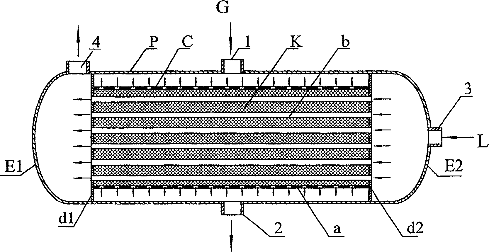
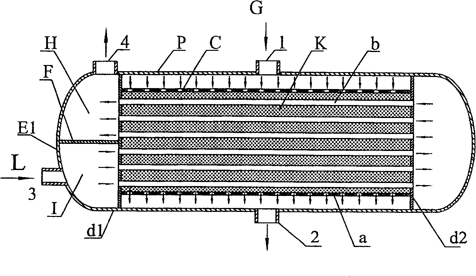
[0049] use Figure 6 A horizontal U-shaped tube synthesis tower for low-pressure methanol synthesis, with an inner diameter of 6.5 meters and a length of 16 meters, filled with NC307 or C302 copper-based methanol, and a catalyst loading capacity of 390m 3 , the synthetic pressure is 8.9MPa, the composition of the gas entering the tower: H 2 63.73%, CO 10.25%, CO 2 5.87%, H 2 O 0.06%, N 2 7.81%, CH 4 12.02%, CH 3 OH 0.28%, the amount of gas entering the tower is 3600000Nm 3 / h, the hot spot temperature of the catalyst layer is 260°C, the output of methanol is 10,000 tons / day, and the by-product steam of 3.8MPa in the heat exchange tube b is heated by reaction heat to 10,000 tons / day. However, under the same conditions and output, the Lurgi shell-and-tube tower needs more than 6 synthesis towers with a diameter of 4 meters, and the investment is more than doubled.

[0050] The subject matter of the present invention has been fully described above through numerous illu...


PUM


Abstract

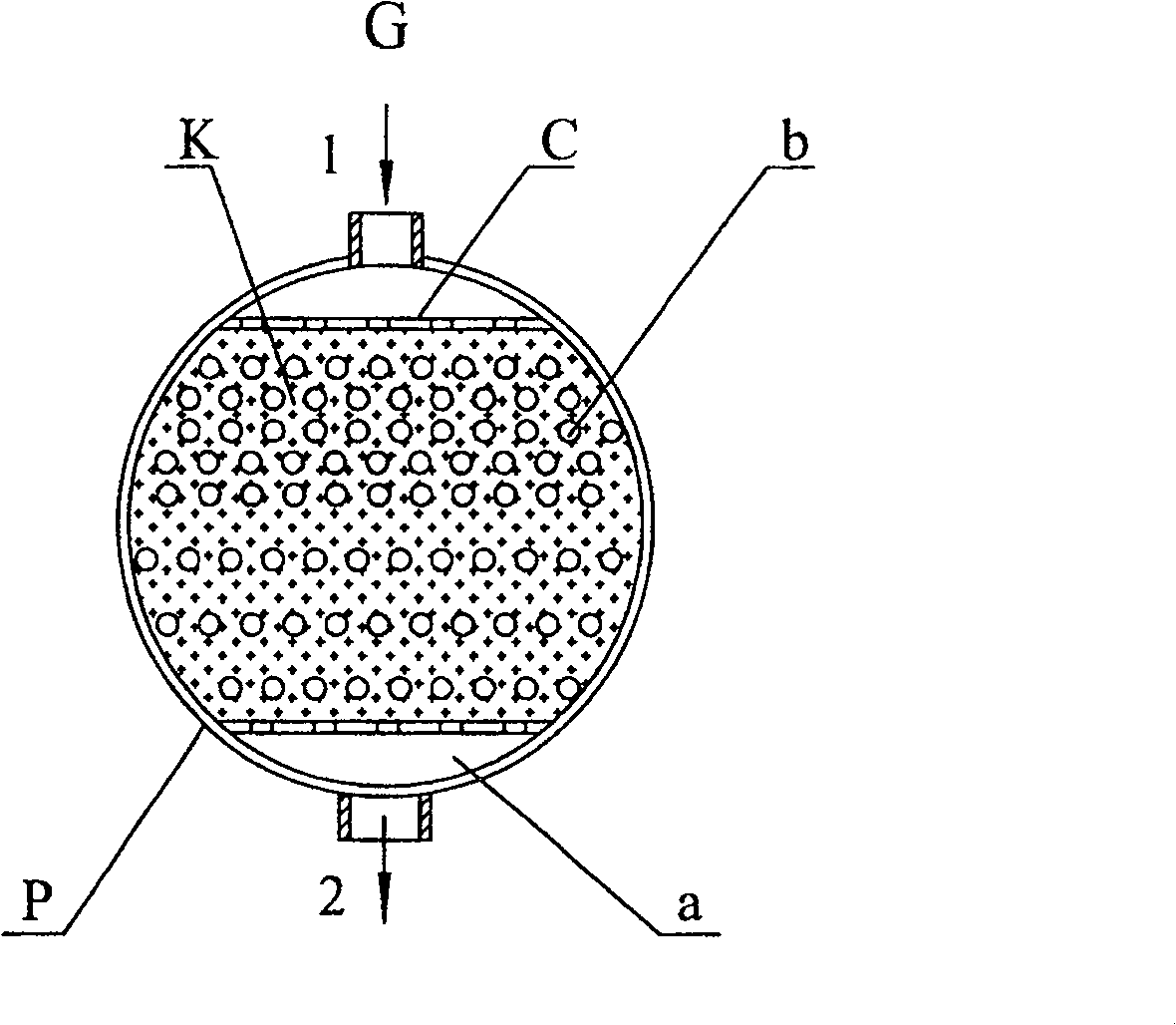
A transverse tubular heat exchange catalytic reaction device, substantially consists of a shell P with a shell cover(s) E, a tube plate(s) (or a circular tube(s)) D linking heat exchange tube(s) B, a porous support plate A supporting the catalyst K, a porous gas distributor C above the catalyst K, a gas inlet 1 and a gas outlet 2 which are on the shell P, a cooling medium inlet(s) 3 and a cooling medium outlet(s) 4 which are on the shell cover(s) E. In the device, the heat exchange tubes B in the catalyst layer are laterally displaced, and the medium in the heat exchange tubes flows laterally. The gas G enters the catalyst layer outside the heat exchange tubes B through the pores of the gas distributor C, flows from top to bottom to react, exchanges heat with the medium L flowing laterally in the heat exchange tubes. It is a reactor with small temperature difference in the catalyst layer, high catalyst activity, high catalyst fill ratio, low layer resistance, simple and reliable structure, and good operational performance.

Description

technical field [0001] The invention is a gas-solid phase catalytic reaction equipment, which is used for fluid catalytic reaction and heat transfer process, belongs to the field of chemical engineering, and is especially suitable for synthetic reaction processes of methanol, methyl ether, hydrocarbons, etc., and can also be used for ethylene oxidation to synthesize epoxy Ethane, vinyl acetate, phthalic anhydride synthesis, ammonia synthesis and other reaction processes. Background technique [0002] For gas-solid phase exothermic catalytic reactions such as synthesis of methanol under pressure, synthesis of methylamine, methyl ether, ammonia, hydrocarbons, etc., as the reaction process progresses, the continuously released reaction heat increases the temperature of the catalyst layer. In order to increase the efficiency of the reactor, it is necessary to remove the reaction heat to lower the reaction temperature. One that was widely used in industrial reactors is multi-sta...

Claims


Application Information

Patent Timeline
Patent Type & Authority Patents(China)
IPC IPC(8): B01J8/02
CPCB01J2208/00884F28D7/16F28D7/12F28D7/06B01J2208/00221B01J2208/00212F28D7/0066B01J2219/182B01J2219/187B01J8/0457B01J8/0496F28F2265/26B01J8/025F28D7/024B01J2208/00132B01J8/0285B01J2208/00141
Inventor 楼寿林楼韧
Owner 杭州林达化工技术工程有限公司
Learn More