Spraying and falling film compound condensation apparatus for coal or biomass pyrolytic liquefaction

A biomass pyrolysis and condensation device technology, used in steam/steam condensers, lighting and heating equipment, etc., can solve the problems of secondary cracking, slow cooling, incomplete condensation, etc., to improve yield and quality, Safe and reliable operation, low cost condensation effect

Inactive Publication Date: 2009-08-19
UNIV OF SCI & TECH OF CHINA
View PDF7 Cites 0 Cited by
  • Summary
  • Abstract
  • Description
  • Claims
  • Application Information

AI Technical Summary

Problems solved by technology

However, practice has proved that this kind of condensing device has the disadvantages of slow cooling speed and incomplete condensation. If the high-temperature pyrolysis vapor cannot be condensed quickly, secondary cracking will easily occur, which will affect the yield and quality of liquid products.
For example, F. Ates et al. reported a self-developed biomass pyrolysis liquefaction device in the literature "Fast Pyrolysis of Sesame Stalk: Bio-oil Yield and Structure Analysis". The pyrolysis gas is condensed. Due to the slow condensation rate, the obtained product is a two-phase product separated by water phase (light oil) and oil phase (heavy oil). The water phase part is difficult to be used as fuel use, while heavy oils are largely unusable due to their high viscosity

Method used


Image

  • Spraying and falling film compound condensation apparatus for coal or biomass pyrolytic liquefaction
  • Spraying and falling film compound condensation apparatus for coal or biomass pyrolytic liquefaction
  • Spraying and falling film compound condensation apparatus for coal or biomass pyrolytic liquefaction

Examples


Embodiment 1

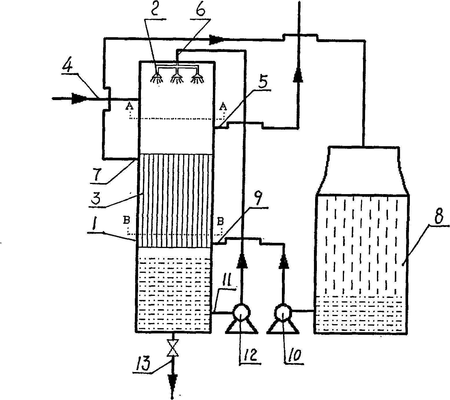
[0023] Taking the spray and falling film compound condensation device in the biomass pyrolysis liquefaction equipment with an oil production capacity of 500kg / h as an example, the condenser 1 has a diameter of 1.5m and a height of 4.5m, and its interior is divided into upper, middle, and For the next three parts, see figure 1 :

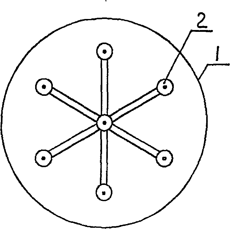
[0024] The upper part is the spray condensation section with a height of 1.5 meters. There are 7 atomizing nozzles 2 installed in the middle of 150mm from the top. figure 2 , the diameter of the nozzle is 0.6mm, which is used to atomize the pyrolysis liquid into fine droplets, which are in direct contact with the high-temperature pyrolysis gas entering from the entrance of the side wall of the condenser (300mm from the top), so that it can be cooled rapidly and condensed;

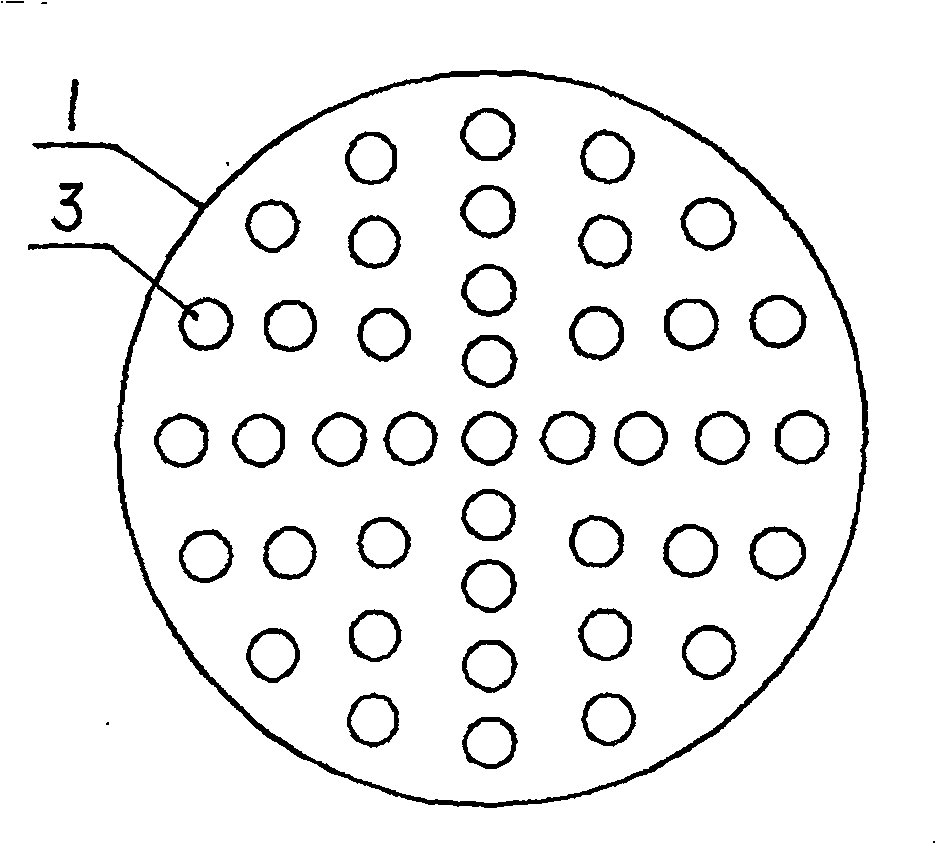
[0025] The middle part is the falling film condensation section, with a height of 1.8 meters. The built-in shell and tube indirect heat exchanger 3 is composed of 600 heat exchan...

Embodiment 2

[0034] Taking the spray and falling film composite condensing device in the biomass pyrolysis liquefaction equipment with an oil production capacity of 50kg / h as an example, the diameter of the condenser is 0.8 meters and the height is 2.5 meters; the height of the spray condensation section in the condenser is 0.8 meters, the height of the falling film condensation section in the middle is 0.8 meters, and the height range of the lower liquid storage section is 0.8 meters.

[0035] The built-in shell and tube indirect heat exchanger is composed of 400 heat exchange tubes with a diameter of 25mm.

[0036] Other structures are with embodiment 1.

Embodiment 3

[0038] Taking the spray and falling film compound condensation device in the biomass pyrolysis liquefaction equipment with an oil production capacity of 800kg / h as an example, the condenser has a diameter of 2.0 meters and a height of 5.0 meters; the height of the spray condensation section in the condenser is 1.5 meters. The height of the falling film condensation section in the middle is 2.0 meters, and the height of the lower liquid storage section is 1.5 meters.

[0039] The built-in shell and tube indirect heat exchanger is composed of 800 heat exchange tubes with a diameter of 25mm.

[0040] Other structures are with embodiment 1.


PUM


Abstract

The invention relates to a spray and falling film composite condensing device for coal or biomass pyrolysis and liquefaction. The cylindrical condenser is divided into upper, middle and lower parts. The upper part is the spray condensation section, and the top is evenly distributed with atomizing nozzles; the middle part is the falling film condensation section, which is equipped with a tubular indirect heat exchanger; Liquid section; also includes liquid transfer pump, cooling tower and corresponding pipeline. Experiments show that this spray falling film composite condenser and its supporting components can well meet the condensation needs of biomass pyrolysis and liquefaction equipment with an oil production capacity of 50-800kg / h, and when straw is used as the raw material for pyrolysis, the liquid The yield of the product is greater than or equal to 50%, and the yield of the liquid product is greater than or equal to 60% when wood chips are used as the raw material for pyrolysis.

Description

technical field [0001] The invention relates to a condensation process device for pyrolysis of coal, biomass and other organic wastes. Background technique [0002] For the pyrolysis and liquefaction of coal, biomass and other organic wastes, the condensing system is generally required to be able to quickly condense the high-temperature pyrolysis vapor to improve the yield and quality of liquid products. The condensing device of the existing pyrolysis liquefaction equipment is mainly composed of a plurality of cooling vessels connected in series, and the high-temperature pyrolysis vapor is condensed through wall cooling. However, practice has proved that this kind of condensing device has the disadvantages of slow cooling speed and incomplete condensation. If the high-temperature pyrolysis vapor cannot be condensed quickly, secondary cracking will easily occur, which will further affect the yield and quality of liquid products. For example, F. Ates et al. reported a self-de...

Claims


Application Information

Patent Timeline
Patent Type & Authority Patents(China)
IPC IPC(8): F28B5/00F28B1/02F28B3/04
Inventor 朱锡锋陆强
Owner UNIV OF SCI & TECH OF CHINA
Why Eureka
Try Eureka