Method for measuring birefraction optical devices phase-delay quantity and fast axis direction and device
A phase delay and optical device technology, applied in the field of laser precision measurement, can solve problems such as poor measurement accuracy, and achieve the effects of simple measurement, doubled measurement accuracy, and simple reception.
- Summary
- Abstract
- Description
- Claims
- Application Information
AI Technical Summary
Problems solved by technology
Method used
Image
Examples
Embodiment 1
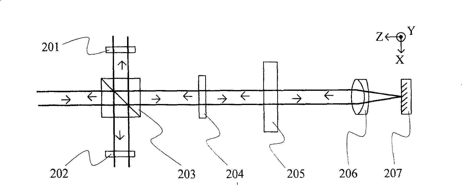
[0041] Measuring method principle of the present invention is as figure 2 As shown, 203 is a beam splitter, 201 and 202 are analyzers, 204 is a half-wave plate, 205 is a sample to be tested, 206 is a converging lens, and 207 is a plane mirror. The beam splitter 203 is a neutral non-polarizing beam splitter. The tested sample 205 has a certain birefringence characteristic, which is characterized by a phase retardation and a fast axis direction, the magnitude of the phase retardation is denoted as Δ, and the angle between the fast axis direction and the X axis is denoted as θ. The included angle between the fast axis direction and the X axis of the half wave plate 204 is denoted as . The incident light contains frequencies f 1 and f 2 The two linearly polarized components of , whose directions are parallel to the X-axis and Y-axis, respectively.
[0042] The orthogonal dual-frequency laser emitted by the laser is used as incident light and is divided into reflected light ...
Embodiment 2
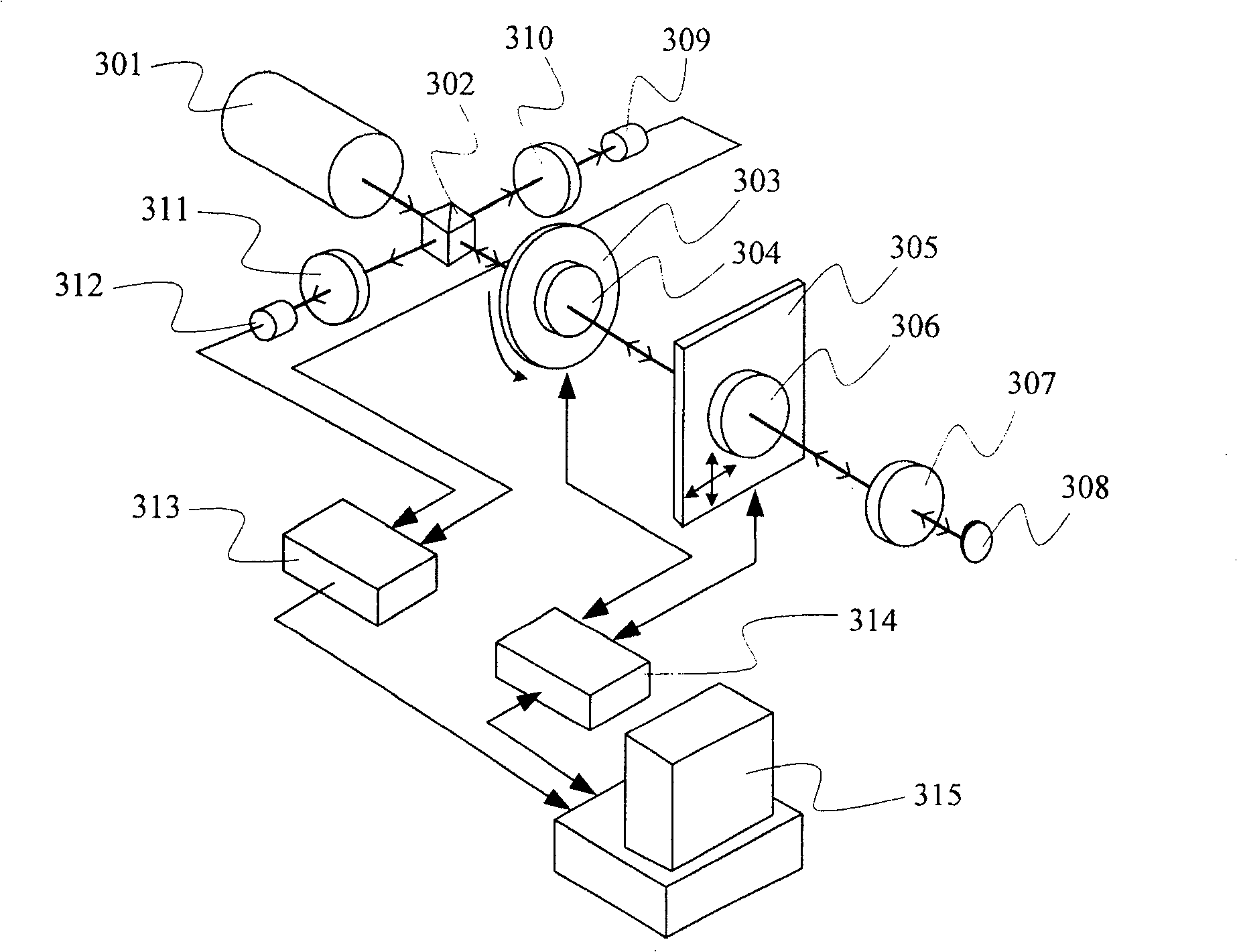
[0053] image 3 It shows a schematic structural view of the measuring device adopting the first embodiment of the method of the present invention, including: a dual-frequency laser light source 301, a beam splitter 302, a rotary table 303, a half-wave plate 304 arranged on the rotary table 303, and a two-dimensional translation Stage 305, measured sample 306, converging lens 307 and plane mirror 308, reference analyzer 311 and reference photodetector 312, measurement analyzer 310 and measurement photodetector 309 respectively arranged on both sides of spectroscope 302, A phase measurer 313 connected to the two photodetectors, a controller 314 connected to the rotating stage and a translation stage, and a computer 315 connected to the phase measurer and the controller.
[0054] In the dual-frequency laser light source, the emitted light contains two orthogonal linearly polarized light components of different frequencies, and the frequency difference between the two is tens of k...
Embodiment 3
[0070] See Figure 4 , is another embodiment of the method of the present invention. Compared with Embodiment 1, the difference is that the half-wave plate 404 is partially located in the optical path. In this embodiment, it is partially placed behind the beam splitter 403. Before, its effect was equivalent to changing the polarization angle of half of the beam of light, while the other half remained unchanged; a wedge-shaped reflector was added to divide the beam returned from the beam splitter 403 into two halves, which were the changed and unchanged polarization angles respectively. The two analyzers 401 and 409 are respectively placed in the light beams separated by the wedge mirror 408 . After the two half-beams of light pass through the polarizers 401 and 409 respectively, they are received to form two measurement beat frequency signals, which are compared with the reference beat frequency signals synthesized by the polarizer 402 to obtain two phase differences. This ca...
PUM
 Abstract
Description
Claims
Application Information
 - R&D
- Intellectual Property
- Life Sciences
- Materials
- Tech Scout
- Unparalleled Data Quality
- Higher Quality Content
- 60% Fewer Hallucinations
Browse by: Latest US Patents, China's latest patents, Technical Efficacy Thesaurus, Application Domain, Technology Topic, Popular Technical Reports.
© 2025 PatSnap. All rights reserved.Legal|Privacy policy|Modern Slavery Act Transparency Statement|Sitemap|About US| Contact US: help@patsnap.com


