Induction heating continuous magnesium-smelting system and continuous magnesium-smelting technique

A technology of induction heating and magnesium smelting, applied in the field of induction heating continuous reduction magnesium smelting system, can solve the problems of increasing the burden of magnesium refining process, increasing secondary loss of magnesium, short life of reduction tank, etc. The effect of improving thermal energy utilization efficiency and reducing labor intensity of workers

Inactive Publication Date: 2009-11-04
CENT SOUTH UNIV
View PDF7 Cites 1 Cited by
  • Summary
  • Abstract
  • Description
  • Claims
  • Application Information

AI Technical Summary

Problems solved by technology

The patent "Induction Heating Reduction Magnesium Smelting Device (CN2265379)" proposes an induction heating magnesium smelting reduction device using electricity as a direct energy source, but this patent inevitably has defects in the external heating method (such as short life of the reduction tank, long reduction time, etc. ), and continuous operations cannot be implemented
The patent "Multiple Heat Sources-Electrothermal Magnesium Smelting Device and Process (CN1928134A)" also proposes a process and equipment for continuous magnesium smelting using AC or DC as energy and Si / C, C or metal materials as radiant heat generated by electrodes. , but there are also some defects in this patent, which are mainly manifested in: ①The heating element arranged in the furnace is easy to cause "bridging" of the charge, and the slag in the hot slag bin may also "bridge"; ②Using powder When feeding, there will inevitably be a large amount of dust in the crystalline magnesium, which not only increases the burden on the magnesium refining process, causes the secondary loss of magnesium to increase, but also may pollute the vacuum system; ③ The obtained crystalline magnesium also needs to be refined, This not only causes the secondary loss of magnesium, but also consumes energy

Method used


Image

  • Induction heating continuous magnesium-smelting system and continuous magnesium-smelting technique

Examples


Embodiment Construction

[0025] The present invention will be described in detail below in conjunction with the accompanying drawings and specific embodiments, but it is by no means intended to limit the scope of the present invention.

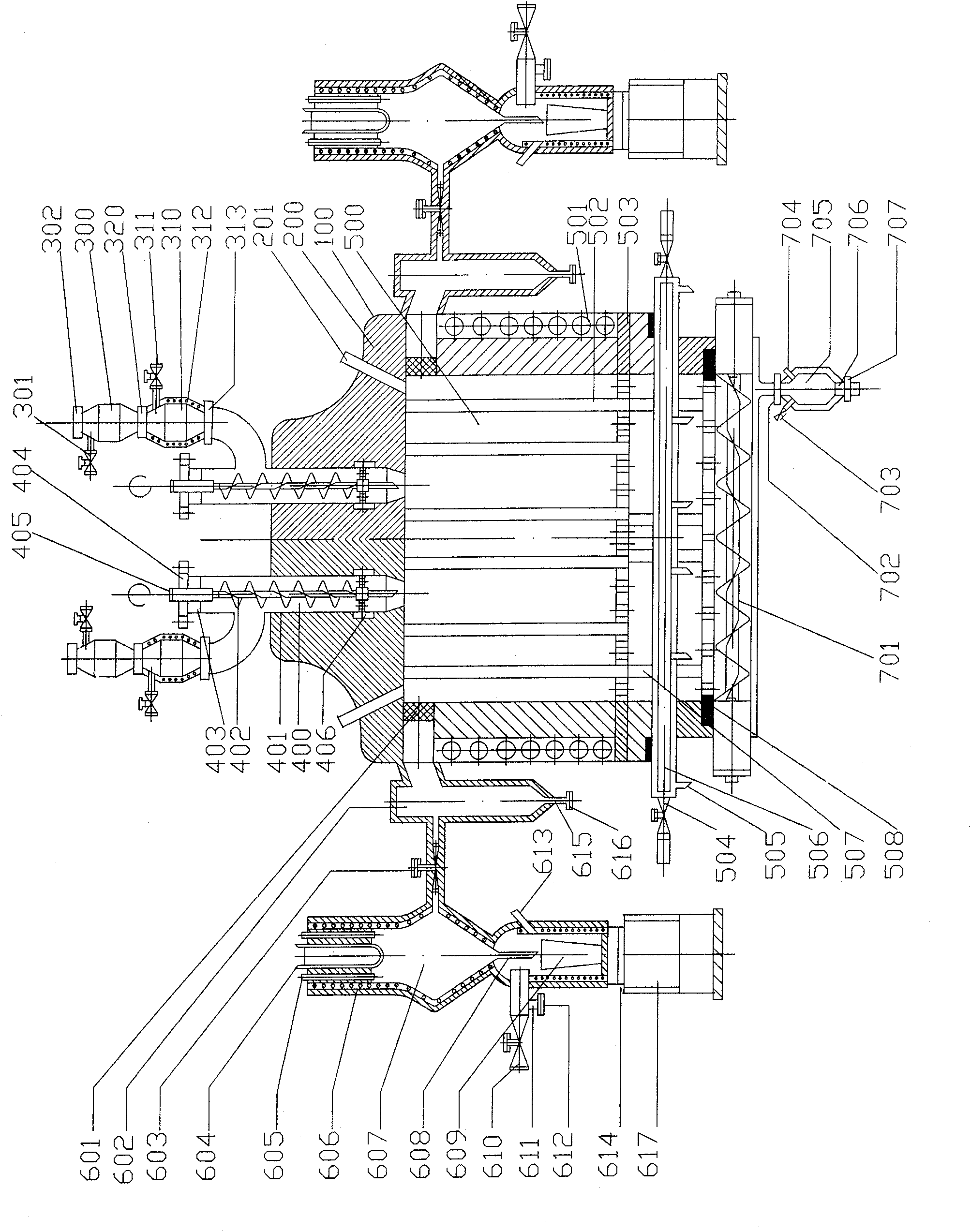
[0026] a. The induction heating continuous magnesium smelting system designed by this patent is shown in the attached figure, including a set of continuous feeding device, an induction heating reaction chamber, two sets of condensing devices for condensing magnesium steam into liquid magnesium, and a set of continuous slagging device .

[0027]b. The furnace shell 100 of the induction heating continuous magnesium smelting system is welded by steel plates, the steel plate is made of A3 steel or No. 45 steel, and the thickness of the steel shell is 10-30 mm; the furnace shell is lined with a heat-insulating refractory layer 200; The furnace body is provided with more than two first observation holes 201, so as to observe the condition of the material level in the furnac...


PUM

PropertyMeasurementUnit
thicknessaaaaaaaaaa
particle sizeaaaaaaaaaa

Abstract

The invention discloses a set of induction heating continuous magnesium smelting device and continuous magnesium smelting process. The device includes a continuous feeding device, an induction heating reaction chamber, a magnesium steam condensing device and a continuous slagging device; wherein, the feeding device is composed of a silo and a screw feeding mechanism, and the reaction chamber is composed of an induction heating coil, a heating element, a belt The baffle plate of the hole and the slag cooling device are composed. The condensing device is composed of a baffle plate with a mesh structure, a dust settling chamber, and a magnesium steam condensing chamber. The continuous slag discharge device includes a spiral slag pushing mechanism and a slag bin. The continuous magnesium smelting process includes the continuous push of the reaction charge into the reaction chamber, the continuous condensation of magnesium vapor, and the discharge of liquid magnesium, as well as the continuous entry of reaction slag into the slag bin and slag discharge. The invention has high thermal energy utilization rate and can realize continuous production of metal magnesium at low cost.

Description

technical field [0001] The invention relates to an induction heating continuous reduction magnesium smelting system, and also relates to a continuous magnesium smelting process using the induction heating continuous reduction magnesium smelting system. Background technique [0002] The production methods of magnesium mainly include thermal reduction method and electrolysis method. At present, 70% of the world's magnesium production is produced by the "Pidgeon method" in the thermal reduction method. However, there are many defects in the current "Pidgeon method" magnesium smelting process, which are mainly reflected in: ① using non-renewable coal or gas petrochemical energy, and directly heating the reduction tank filled with pellets in the air The method not only makes the effective utilization rate of heat energy low and the life of the reduction tank is short, but also makes it difficult for the heat to quickly transfer to the center of the reduction tank, making the redu...

Claims


Application Information

Patent Timeline
Patent Type & Authority Patents(China)
IPC IPC(8): C22B26/22C22B5/16
Inventor 周向阳李劼丁凤其徐日瑶伍上元
Owner CENT SOUTH UNIV
Why Eureka
Try Eureka