Reverse dust collector with eddy plate

A dedusting device and reverse technology, applied in waste heat treatment, energy industry, cement production, etc., can solve problems such as boiler wear, heat exchange efficiency drop, damage, etc., to reduce maintenance costs, eliminate load increase, suppress wear and damage effect

Active Publication Date: 2010-01-20
KAWASAKI HEAVY IND LTD
View PDF6 Cites 0 Cited by
  • Summary
  • Abstract
  • Description
  • Claims
  • Application Information

AI Technical Summary

Problems solved by technology

However, in order to achieve the purpose, it is necessary to increase the dust removal accuracy in the case of different particle sizes (for example, 0.3mm or more), which wear and damage the boiler
On the other hand, when dust of medium particle size (for example, less than 0.3 mm) is completely removed and only fine dust remains, the adhesion and lamination of fine dust on the heat exchange surface of the boiler remarkably proceed, and thus it is found that the heat exchange efficiency is lower. fall early

Method used


Image

  • Reverse dust collector with eddy plate
  • Reverse dust collector with eddy plate
  • Reverse dust collector with eddy plate

Examples


Embodiment Construction

[0058] Hereinafter, embodiments of the present invention will be described with reference to the drawings.

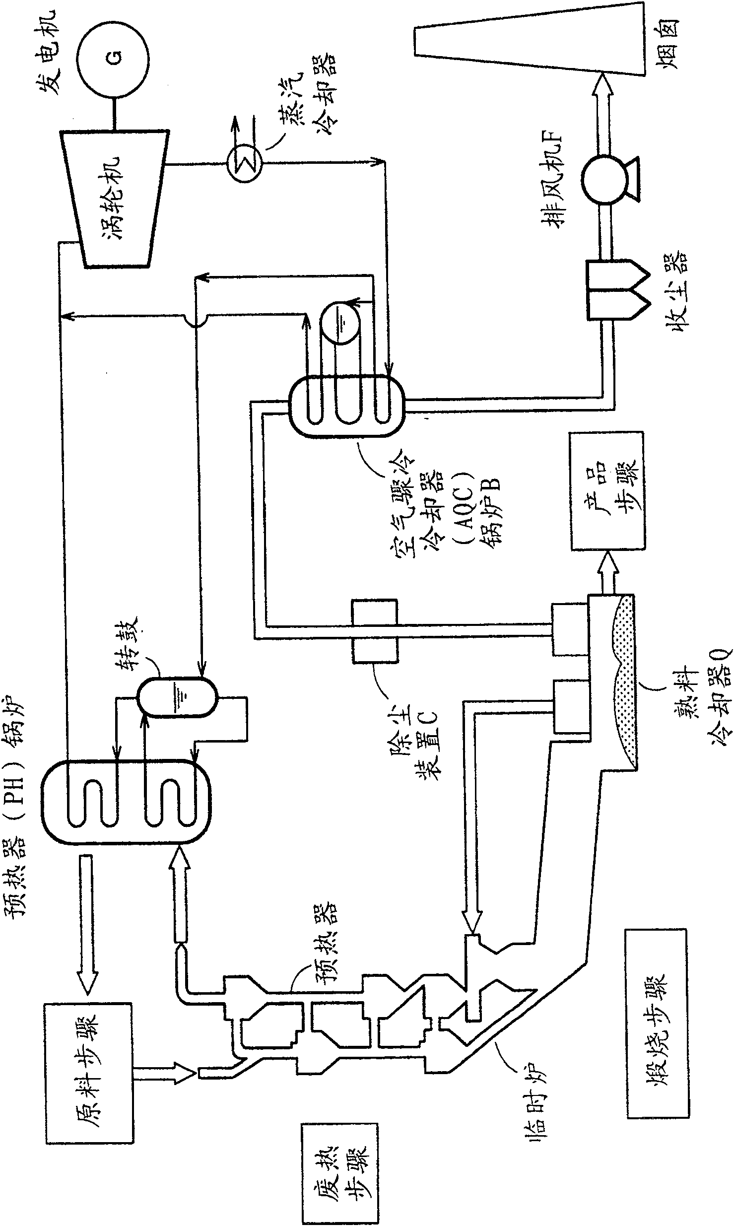
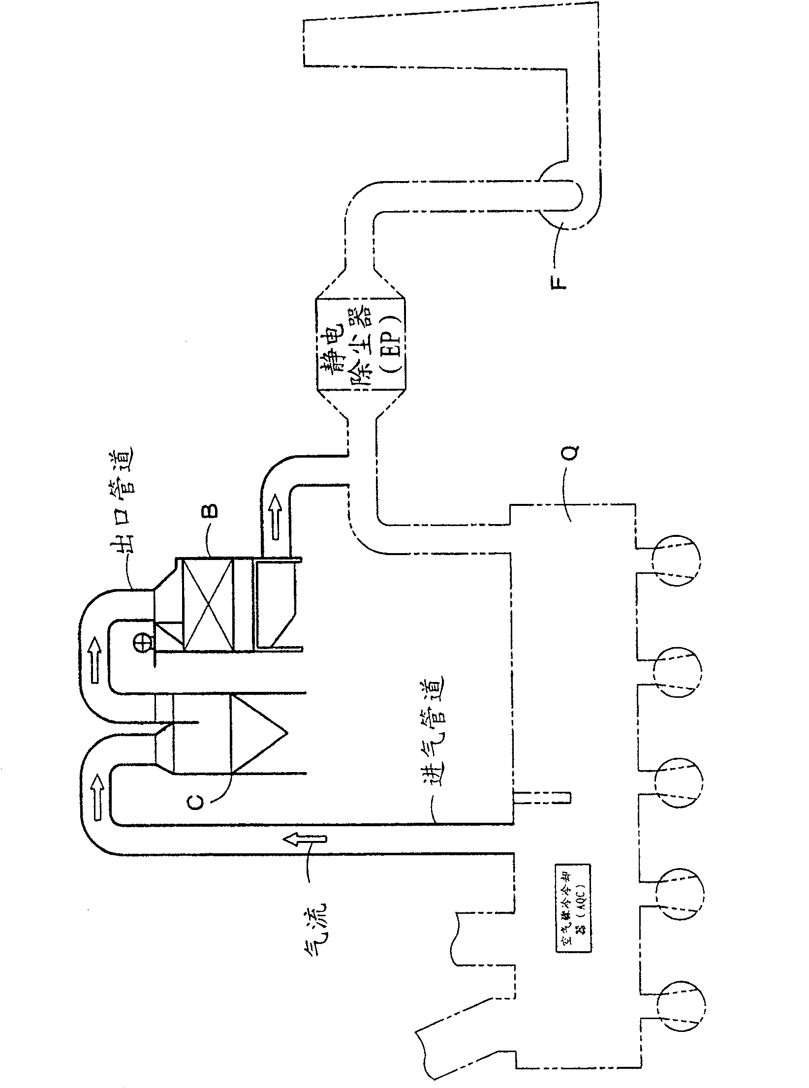
[0059] This embodiment is a system in which the exhaust gas at a higher temperature discharged from the intermediate stage of the air quench cooler Q as a clinker cooler is processed through a dust removal device (dust collector) C for dust removal ,Such as figure 2 shown in . Next, the exhaust gas is supplied to the AQC boiler B, returns to the exhaust pipe, is discharged through the exhaust fan F, and is discharged from the chimney.

[0060] Exhaust gas discharged from the intermediate stage of the air quench cooler (AQC) Q and supplied to the AQC boiler B (at about 360°C and a flow rate of 1800Nm 3 / min) includes a large amount of dust having diameters of various sizes, such as a particle diameter of 1.0 mm or less. Exhaust flow rate is about 1800Nm 3 / min, and is discharged at a flow rate of 15m / s through the exhaust fan on the downstream side of AQC boiler B. ...


PUM

PropertyMeasurementUnit
particle diameteraaaaaaaaaa

Abstract

The invention provides a reverse rotation dedusting device, comprising a main unit. The main unit is a rectangle box. An ash hopper is arranged on the lower part of the main unit and comprises four inclined surfaces. The upper space of the main unit is divided into an air inlet chamber and a separation chamber through a baffle plate. The lower space of the main unit is provided with a plurality of vertical baffles basically along an inclined surface of the ash hoppers; a gas flow route is formed between all baffle plates and the inclined surfaces, in convenient for wide upstream side and a narrow downstream side. The baffle plate on the upstream side is long in the vertical direction; furthermore, the interval between all baffle plates has narrow upstream side and wide downstream side. The airflow in the gas flow route ascends along the baffle plate and is rectified on the upstream side through the baffle plate; the baffle plate is long in the vertical direction, so as to lead the airflow to be basically a lamellar flow and to flow into the separation chamber. The flowing speed of the airflow is restricted by flow resistance between the baffle plates, thus leading the flowing speed to be more uniform.

Description

technical field [0001] The present invention relates to a dedusting device for removing dust from gas discharged from a heat material cooler with a waste heat recovery system, eg in a cement plant. [0002] Although the present invention relates to a dedusting device generally used in an exhaust gas system of a cement plant, the present invention can be applied to exhaust gas systems of other factories such as steel mills, which are equipped to recover dust from the exhaust gas mixed with hard dust. Waste heat boiler. Background technique [0003] Schematic diagram of a cement plant in figure 1 shown in and generally known. In cement plants, research and dissemination of heat recovery technologies are promoted for energy conservation. An example of this is in figure 1 shown in . [0004] exist figure 1 In the cement plant shown, the waste heat of the gas discharged from the preheater is recovered by a PH (preheater) boiler, while the gas discharged from the air quench ...

Claims


Application Information

Patent Timeline
Patent Type & Authority Patents(China)
IPC IPC(8): B01D45/02F27D17/00F23J15/02
CPCY02P40/121Y02P80/15
Inventor 反田克史竹中幸弘酒井雅久
Owner KAWASAKI HEAVY IND LTD
Why Eureka
Try Eureka