Evaporation source device
An evaporation source and evaporation part technology, applied in vacuum evaporation plating, ion implantation plating, metal material coating process, etc., can solve the problems of sputtering, complicated operation, difficult to obtain large evaporation, etc., to achieve the finished product rate increase effect
- Summary
- Abstract
- Description
- Claims
- Application Information
AI Technical Summary
Problems solved by technology
Method used
Image
Examples
Embodiment 1
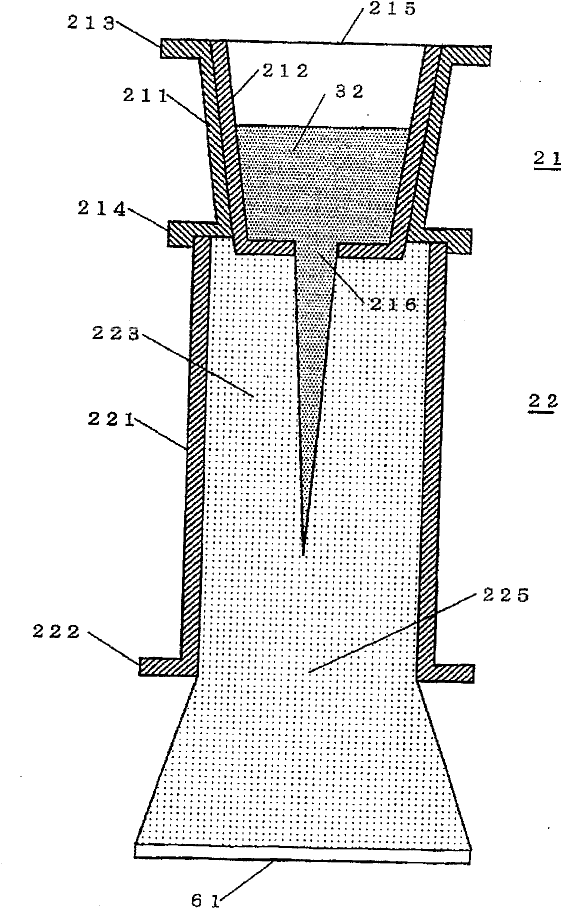
[0074] figure 1 A cross-sectional view of the evaporation source device of Example 1 is shown.
[0075] The crucible is heated by resistance heating. The heating method may also adopt other heating methods such as electron bombardment.
[0076] The evaporation source device includes: a retention unit 21 for storing and retaining the melted and liquefied evaporation material; an evaporation unit 22 for heating the melted and liquefied evaporation material to a vaporizable temperature to evaporate it; and a sprayer for spraying steam to the substrate 61 Use opening 225.
[0077] The retention unit 21 includes a cylindrical heating element 211 capable of conducting electricity and a heating container 212 of an electrical insulator accommodated therein. figure 1 The structure of the retention portion 21 is based on the premise that the molten evaporating material 32 is a conductive substance, but when the fused evaporating material 32 is an electrical insulator, the cylindric...
Embodiment 2
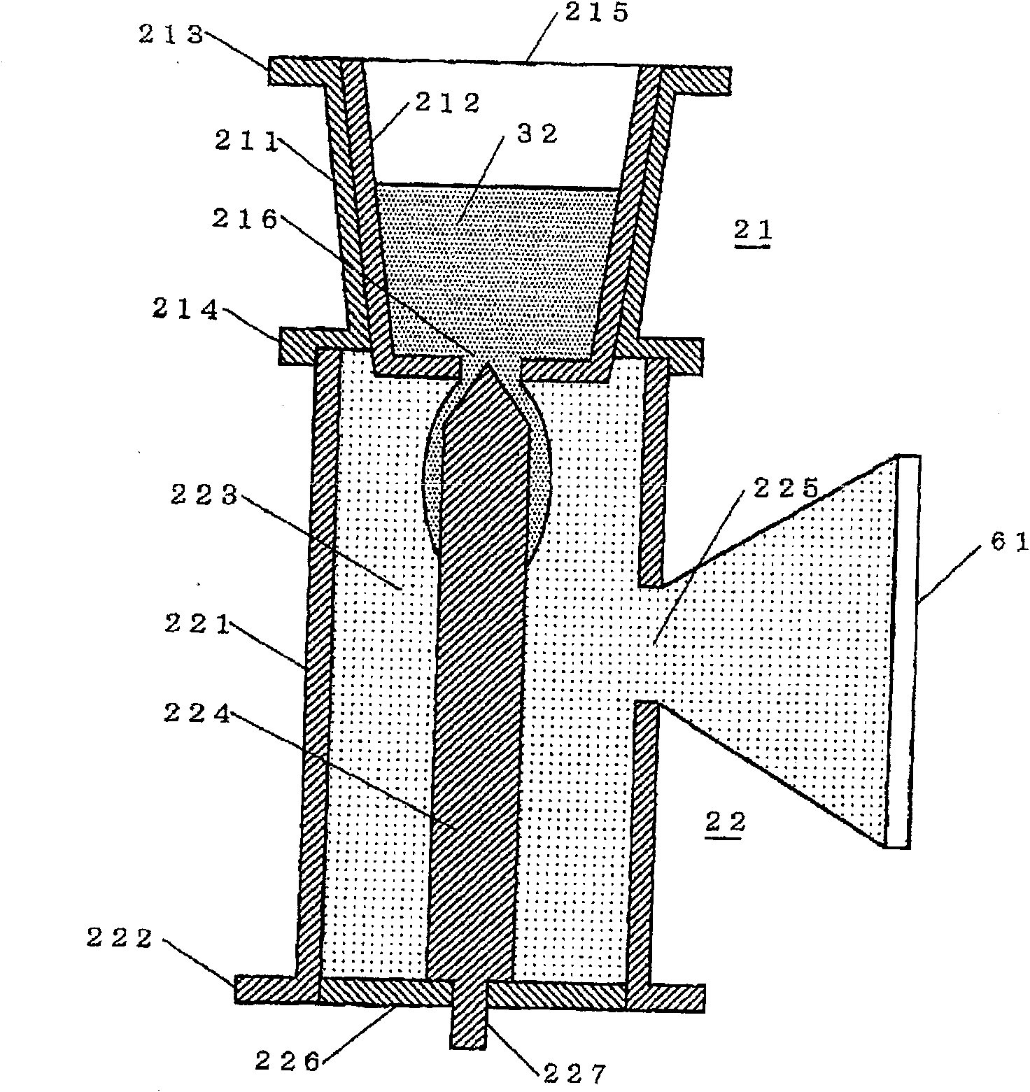
[0092] figure 2 A cross-sectional view of the evaporation source device of Example 2 is shown.
[0093] exist figure 1 In the case of evaporative material 32, the descending speed of evaporative material 32 falling in cylindrical heating element 221 is determined by the viscosity and gravity of evaporative material 32, so when increasing the descending amount of evaporative material 32 in order to increase the amount of evaporation of evaporative material 32, Then, the lowering time until the evaporation material 32 is completely evaporated becomes longer. To prolong the lowering time, it is necessary to increase the height of the cylindrical heating element 221 . Therefore, in order to easily manufacture and operate the evaporation source device, it is required to prolong the lowering time of the evaporation material 32 without increasing the height of the cylindrical heating element 221 .
[0094] To meet this requirement, figure 2 The evaporation source device is pro...
Embodiment 3
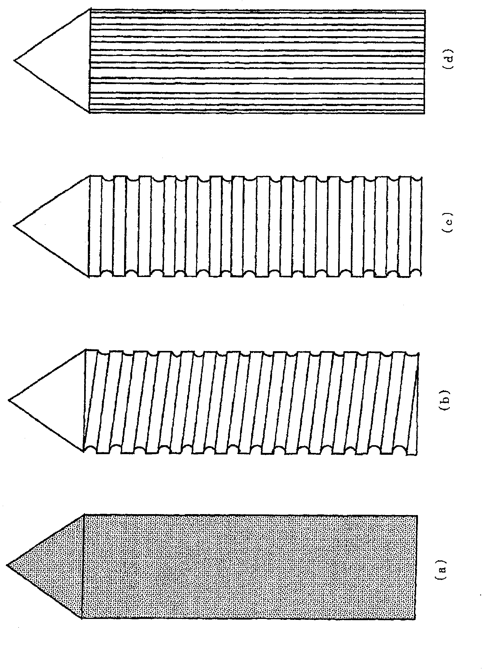
[0100] image 3 express figure 2 An embodiment of the columnar body 224 for lowering.
[0101] image 3 Four surface shapes of the lowering column are shown. The descending columnar body changes the descending speed and wetted area (diffusion area) of the molten evaporation material according to the surface shape.
[0102] image 3 The drop of (a) forms small irregularities on the surface with a columnar body or forms the surface in a pear-like shape, image 3 (b) The columns for lowering form spiral grooves on the surface, image 3 (c) The lowering columnar body forms a horizontal annular groove on the surface, image 3 The columnar body for lowering (d) has grooves in the vertical direction (axial direction of the columnar body for lowering) formed on the surface.
[0103] pass image 3 The surfaces of the lowering columns (a) to (d) are uneven, so that the lowering speed of the evaporating material can be slowed down, and the effect of radiant heat on the evaporati...
PUM
 Abstract
Description
Claims
Application Information
 - R&D
- Intellectual Property
- Life Sciences
- Materials
- Tech Scout
- Unparalleled Data Quality
- Higher Quality Content
- 60% Fewer Hallucinations
Browse by: Latest US Patents, China's latest patents, Technical Efficacy Thesaurus, Application Domain, Technology Topic, Popular Technical Reports.
© 2025 PatSnap. All rights reserved.Legal|Privacy policy|Modern Slavery Act Transparency Statement|Sitemap|About US| Contact US: help@patsnap.com


