Aligning system used for photolithography equipment

An alignment system and lithography equipment technology, applied in the field of lithography machines, can solve the problems of inability to reliably provide the highest alignment accuracy, inability to utilize high-order signals, low power, etc., so as to reduce the signal processing time overhead, simplify the The difficulty of optical path design and debugging, the effect of strong signal strength

Active Publication Date: 2010-02-03
SHANGHAI MICRO ELECTRONICS EQUIP (GRP) CO LTD
View PDF10 Cites 0 Cited by
  • Summary
  • Abstract
  • Description
  • Claims
  • Application Information

AI Technical Summary

Problems solved by technology

The advantage of this scheme is that it can achieve automatic capture and high alignment accuracy, but the disadvantage is that it requires a special wedge adjustment device and complicated adjustment. In addition, the high-order signals in the diffracted light are weak, while this method is Higher alignment accuracy is achieved by relying on high-order signals. In practice, as the power of the reflected signal (especially the high-order signal) of the mark (especially the silicon wafer mark) is too low, the high-order signal cannot actually be used. Therefore, it cannot reliably provide the highest alignment accuracy

Method used


Image

  • Aligning system used for photolithography equipment
  • Aligning system used for photolithography equipment
  • Aligning system used for photolithography equipment

Examples


Embodiment Construction

[0045] The specific embodiments of the present invention will be further described below in conjunction with the accompanying drawings.

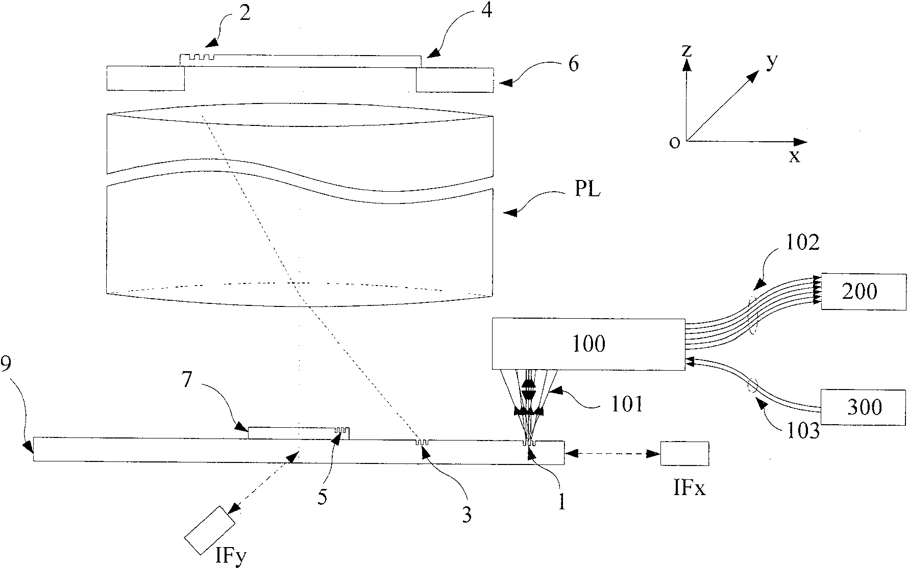
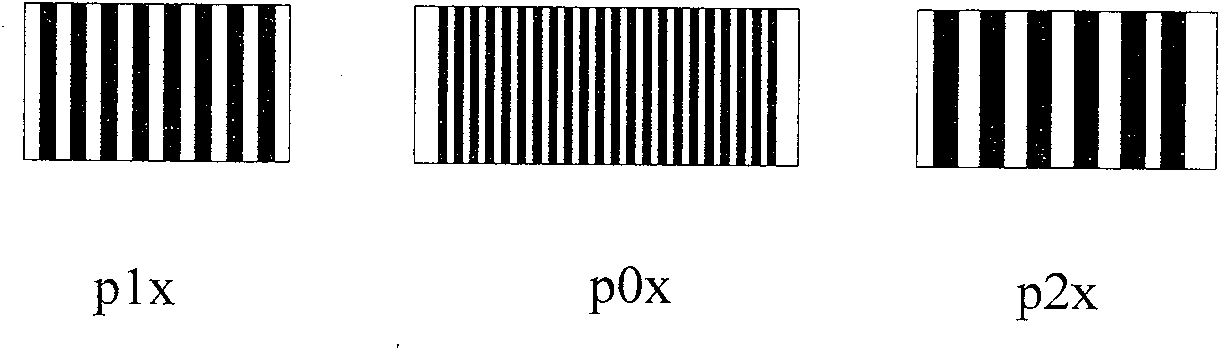
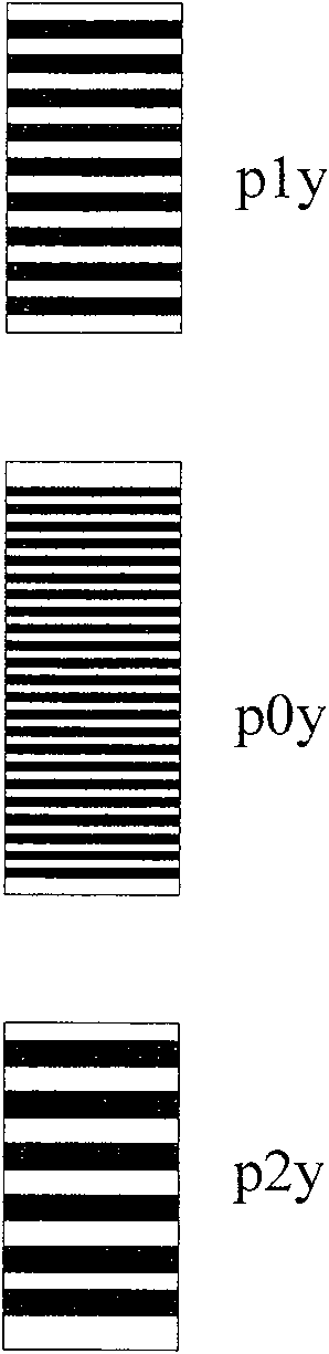
[0046] attached figure 1 ( figure 1 It is a schematic diagram of the alignment system of the lithography machine using the present invention) showing an alignment system used in the prior art and an embodiment that can be adopted by the alignment system of the present invention. The main structure of the lithography machine includes: a mask table 6. Mask plate 4, projection objective lens PL, substrate table 9. Substrate table mark 1 and substrate mark 5 can be figure 2 , image 3 or Figure 4 form. The distribution of substrate mark 5 on substrate 7 can be Figure 15 or Figure 16 in the form of, among them, Figure 15 It is a combination of 4 groups of one-dimensional three-period marks.

[0047] In the system used in the prior art, a lower-energy exposure radiation source or other non-exposure wavelength radiation source is used...


PUM

PropertyMeasurementUnit
diffraction angleaaaaaaaaaa

Abstract

The invention discloses an alignment system applied in a lithography device, which uses three periods phase grating with crude precision combination in a substrate marker or a substrate station reference marker, uses a first order diffraction light of the three periods as an alignment signal, simultaneously realizes a big capture range and gets high alignment precision, gets labeled deformation information and other useful information, and through the optimum design of the match and / or the layout of the three periods, the influence on an alignment position by asymmetrical deformation of the marker is effectively reduced.

Description

technical field [0001] The invention relates to lithography machine technology, in particular to the alignment technology of scanning projection lithography machine. Background technique [0002] Applying a step-and-scan projection lithography machine to complete the pattern transfer task of micromachining basically involves basic steps such as workpiece loading, alignment of the workpiece area to be processed with the mask, workpiece exposure, and workpiece unloading. In the case of multi-layer processing technology, the precise alignment of the workpiece area to be processed and the mask plate is the premise to ensure that the workpiece is correctly processed when the line width is continuously reduced. When the graphics are accurately projected to the workpiece area to be processed or a new layer When the accurate registration of the graphics is projected on the area of ​​the previously formed workpiece to be processed, the proper exposure of the current layer can realize...

Claims


Application Information

Patent Timeline
Patent Type & Authority Patents(China)
IPC IPC(8): G03F9/00G03F7/20
Inventor 韦学志李运锋徐荣伟周畅陈勇辉
Owner SHANGHAI MICRO ELECTRONICS EQUIP (GRP) CO LTD
Why Eureka
Try Eureka