Method for constituting conformal bearing microstrip antenna structure based on three dimension orthogonal machine woven fabric

A microstrip antenna and woven fabric technology, applied in the direction of antenna, radiating element structure, electrical components, etc., can solve the problems of structure delamination, antenna system failure, collapse, etc., and improve damage resistance and shape adaptability. Strong and complete effect

Inactive Publication Date: 2007-07-25
DONGHUA UNIV
View PDF0 Cites 4 Cited by
  • Summary
  • Abstract
  • Description
  • Claims
  • Application Information

AI Technical Summary

Problems solved by technology

Although this structure is a big step forward than the previous structure, it is found through experiments that the failure form after it is stressed is still layered.
Foreign researchers You et al. made a multi-layer microstrip antenna structure on the basis of CLAS, that is, put the microstrip antenna into the sandwich structure by layer and method, and the whole system can withstand certain mechanical effects, especially Under impact load, the structure is prone to serious damage such as delamination and collapse, and the entire antenna system will fail

Method used


Image

  • Method for constituting conformal bearing microstrip antenna structure based on three dimension orthogonal machine woven fabric
  • Method for constituting conformal bearing microstrip antenna structure based on three dimension orthogonal machine woven fabric

Examples


Embodiment 1

[0031] Referring to Fig. 1, 2, the present invention constitutes the method for the conformal carrying microstrip antenna structure based on three-dimensional orthogonal woven fabric, mainly comprises the following steps:

[0032] (1) Select a fiber suitable as a three-dimensional composite material reinforcement, and weave it into a three-dimensional orthogonal fabric on a three-dimensional orthogonal loom;

[0033] (2) select a kind of resin to make the three-dimensional composite material by dipping the three-dimensional orthogonal woven fabric, test and calculate the dielectric constant and dielectric loss of the three-dimensional composite material;

[0034] (3) Utilize the dielectric constant of the obtained composite material to calculate the basic size of the microstrip antenna radiating element, and weave the basic structure prefabricated part of the microstrip antenna on the three-dimensional loom according to the size of the designed radiating element;

[0035] (4) ...

Embodiment 2

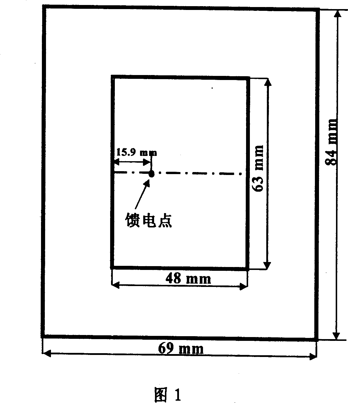
[0043] Refer to Figure 1, design the integrated structure of dipped antenna-three-dimensional composite material

[0044] 1. Select aramid fiber as the basic reinforcement of the composite material, choose Shanghai Fuchen Chemical 854 type bisphenol A epoxy vinyl resin as the resin, and use the transmission-reflection method to test and calculate the dielectric constant of the composite material to be 4;

[0045] 2. Design antenna radiating element size (dielectric constant is 4, substrate thickness is 4.5mm, resonant frequency is 1.5GHz) to calculate the antenna size parameters, as shown in Figure 1;

[0046] 3. Weaving prefabricated parts of 3D microstrip antenna

[0047] The three-dimensional fabric warp yarn is designed to be six layers, and the warp and weft yarns of the bottom layer are replaced by copper stranded wires, and the rest of the warp and weft yarns and the yarns in the Z direction are all aramid fibers. When weaving length along the warp direction reaches 10...

Embodiment 3

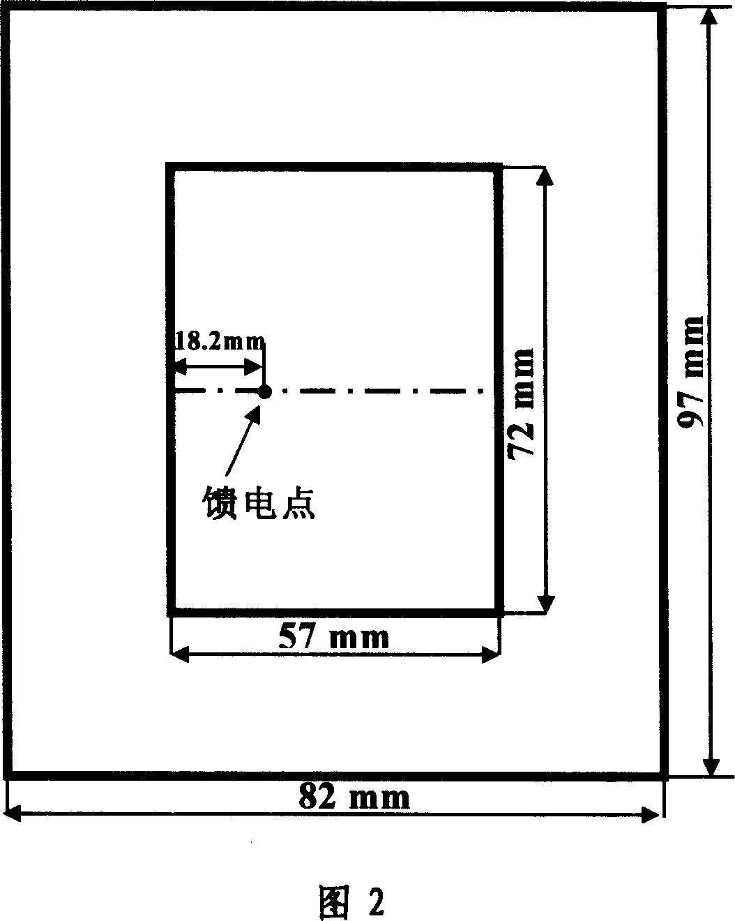
[0051] Refer to Figure 2, design the antenna-three-dimensional composite material integrated structure without dipping

[0052] (1) Design antenna radiating element size (dielectric constant is 2.8, substrate thickness is 4.5mm, resonant frequency is 1.5GHz)

[0053] (2) Weaving the prefabricated part of the three-dimensional microstrip antenna

[0054] The three-dimensional fabric warp yarn is designed to be six layers, and the warp and weft yarns of the bottom layer are replaced by copper stranded wires, and the rest of the warp and weft yarns and the yarns in the Z direction are all aramid fibers. When weaving length along the warp direction reaches 12.5mm, the first and second layers of warp yarns behind the three-dimensional loom are raised from the middle along the weft direction to a width of 57mm, and the yarns that have not been lifted in the two layers of yarns are combined by a layering device. Together, the yarn in the Z direction of the upper layer and the 57mm y...


PUM


Abstract

The method includes steps: weaving the selected fiber into 3D orthogonal textile by using 3D orthogonal weaving machine; cement dipping 3D orthogonal textile to selected resin to produce 3D composite material, and measuring and calculating dielectric constant and dielectric loss of 3D composite material; using the dielectric constant to calculate basic size of radiating element of microstrip antenna, and weaving precast product of basic structure of microstrip antenna; using method of interweaving conduction wire and yarn of textile fiber to constitute radiating element above antenna and earth-plate at low place; the said radiating element and earth-plate are as top layer and bottom layer in 3D weaving structure. The 3D weaving structure possesses features of good integrality, high impact resistance, and not easy of layering. Combining with 3D textile in an integrated structure, the microstrip antenna becomes an inseparable part in the entirety of antenna and textile.

Description

technical field [0001] The invention relates to a microstrip antenna capable of bearing external force and receiving transmitted signals, in particular a method for forming a conformal microstrip antenna structure based on a three-dimensional orthogonal woven fabric. Background technique [0002] Antennas are the eyes and ears of wireless communications. In the fields of aerospace, field exploration and people's daily life, antennas are increasingly becoming the main tool for people to send and receive signals. Modern aircraft need to install a large number of antennas for effective long-distance communication. Traditional communication antennas use a protruding structure. Although this structure is effective, it increases air resistance because it protrudes from the surface of the fuselage structure. Moreover, for the installation of the antenna, it is necessary to set grooves or holes on the surface of the original complete structure, which damages the structural integri...

Claims


Application Information

Patent Timeline
Patent Type & Authority Applications(China)
IPC IPC(8): H01Q13/08H01Q1/38
Inventor 姚澜邱夷平
Owner DONGHUA UNIV
Why Eureka
Try Eureka