
Speed control method for AC motor servo system

A servo system and AC motor technology, applied in the direction of motor generator control, electronic commutation motor control, control system, etc., can solve the problem of measurement noise sensitivity, inability to target speed and dynamic response performance, design controller, and observer stability analysis Difficulty and other issues

Inactive Publication Date: 2007-07-25
SHANGHAI JIAO TONG UNIV
View PDF0 Cites 30 Cited by
  • Summary
  • Abstract
  • Description
  • Claims
  • Application Information

AI Technical Summary

Problems solved by technology

[0003] After searching the literature of the prior art, it was found that the MT proposed by Brown et al. in the article Analysis of algorithms forvelocity estimation from discrete position versus time data (IEEE Trans.Ind.Electron., 1992, 39, 5, PP.11-19) (Measuring frequency & measuring period) method, its disadvantage is: in the case of low-speed operation, especially when the pulse interval time is much longer than the speed sampling period, the detection time delay caused by the MT speed measurement method can easily make the controller unstable. , so it is difficult to obtain ideal speed response characteristics and servo performance
[0004] For the problem of speed detection time delay at low speeds, vector control method and load observation method are currently used more methods. This method has a simple circuit, but because the mathematical model of the motor is nonlinear, the stability analysis of the observer is very difficult. Dependence on motor parameters, this method must solve the adaptive problem of speed and position estimation to motor parameters and load disturbance, and the sensitivity to measurement noise. Conventional methods cannot design controllers according to target speed and dynamic response performance
Therefore, the general observer control method has poor speed tracking accuracy, is very sensitive to measurement noise at low speeds, and has overshoot and oscillation phenomena corresponding to the dynamic output position of the step input command signal

Method used


Image

  • Speed control method for AC motor servo system
  • Speed control method for AC motor servo system
  • Speed control method for AC motor servo system

Examples


Embodiment Construction

[0019] The embodiments of the present invention are described in detail below in conjunction with the accompanying drawings: this embodiment is implemented on the premise of the technical solution of the present invention, and detailed implementation methods and specific operating procedures are provided, but the protection scope of the present invention is not limited to the following the described embodiment.

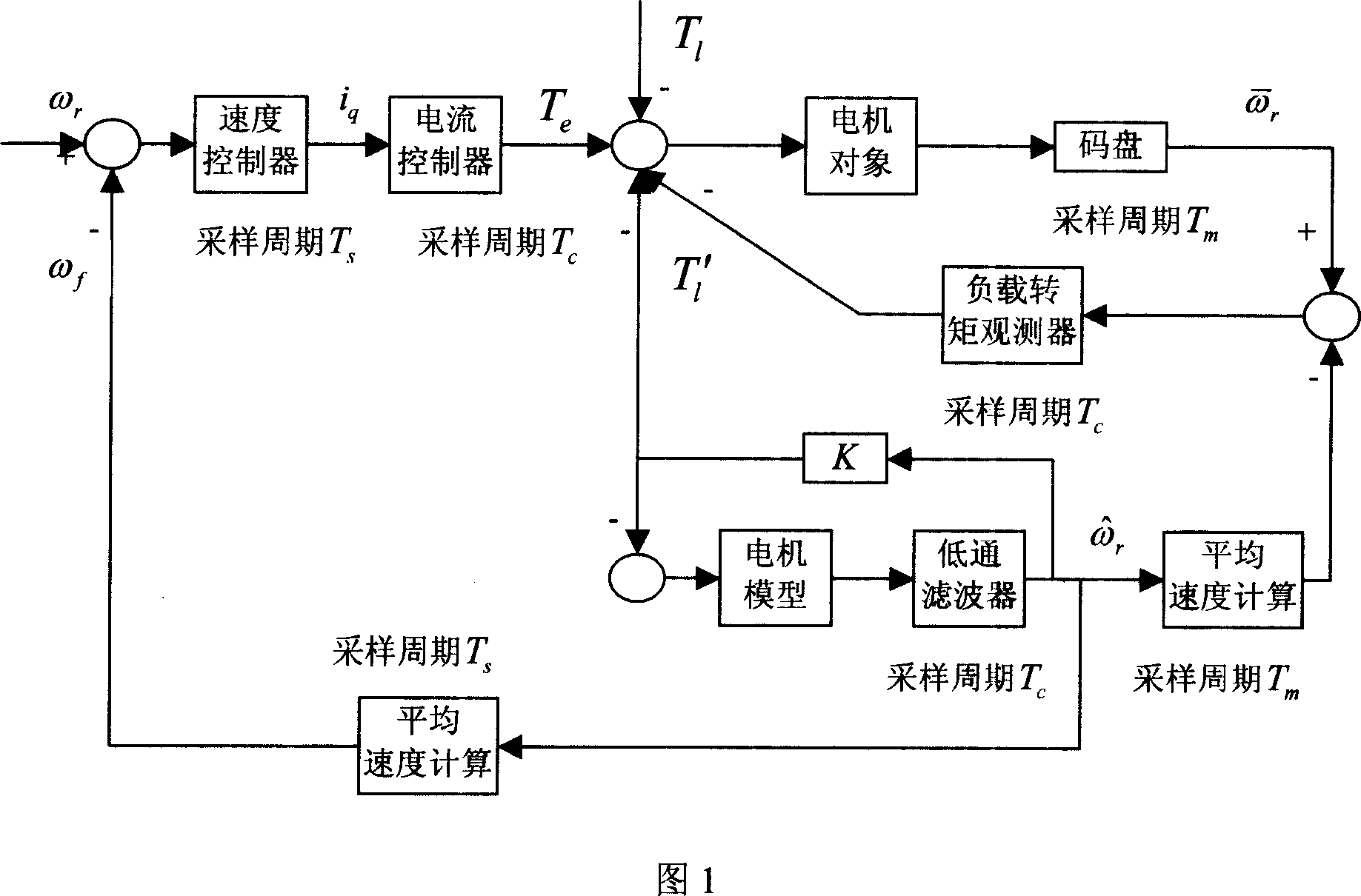
[0020] As shown in Figure 1, after the system enters the control stage, the user sets the target speed ω according to the actual motor working conditions r , in order to ensure the correctness of the velocity observer, the control variable ω f As feedback quantities, observers are used to predict load torque disturbances and continuous speed changes at low speeds in real time. First use the sampling period T s The speed controller performs speed signal detection and transmission, and at the same time uses the sampling period T c The current controller detects and t...


PUM


Abstract

The disclosed method for controlling speed of servo system of AC motor combines inner and outer two control rings. In the inner control ring, using coded disc measures speed of motor based on object of motor. Using load - torque observer carries out feedback control. In the outer control ring, using model of electrical motor through lowpass filter obtains estimated speed of rotor. Calculated average speed is input to feedback loop so as to form feedback control in close loop for whole control system. The method possesses high load capacity and capacity of anti external interference. The invention is suitable to control speed of AC servomotor.

Description

technical field [0001] The invention relates to a method in the technical field of motor control, in particular to a speed control method of an AC motor servo system. Background technique [0002] AC motors are widely used in modern AC servo systems because of their small size, high reliability, and excellent servo performance. Low-speed performance is one of the important indicators of servo system performance. The servo drive device is an important part of high-performance machine-integrated products such as CNC machine tools and industrial robots, and is also an indispensable basic unit for factory automation. At present, scholars from various countries have proposed many methods to complete the control of motor speed tracking accuracy. [0003] After searching the literature of the prior art, it was found that the MT proposed by Brown et al. in the article Analysis of algorithms forvelocity estimation from discrete position versus time data (IEEE Trans.Ind.Electron., 19...

Claims


Application Information

Patent Timeline
IPC IPC(8): H02P21/00H02P21/13H02P21/18
Inventor 胡明慧王永山黎华邵惠鹤
Owner SHANGHAI JIAO TONG UNIV
Learn More