Pulse pendulum type monopropellant engine

A pendulum engine, single-component technology, applied in the direction of swing piston engine, rotary or swing piston engine, engine components, etc., can solve the problem of system energy density and power density reduction, system energy and power density reduction, chemical battery energy Low density and other problems, to achieve the effect of reducing friction loss, easy starting and compact structure

Inactive Publication Date: 2007-08-01
SHENZHEN GRADUATE SCHOOL TSINGHUA UNIV
View PDF0 Cites 4 Cited by
  • Summary
  • Abstract
  • Description
  • Claims
  • Application Information

AI Technical Summary

Problems solved by technology

However, these energy or power supply devices have some disadvantages: the low energy density of chemical batteries makes it difficult to work for a long time; although fuel cells have higher energy density than chemical batteries, even without considering their hydrogen storage Technical difficulties, due to its low power density, it is difficult to be suitable for applications that require rapid power increase; for the same output power, the electric actuators used in conjunction with the above-mentioned chemical or fuel cells are generally larger than hydraulic or pneumatic actuators. Bulky, so will result in lower system energy and power density
For small internal combustion generator sets, although gasoline or diesel has a high energy density, all hydrocarbon fuel engines require complex auxiliary subsystems such as compression and ignition in addition to their own moving parts such as crankshafts and pistons; in addition, Small internal combustion engines must operate at very high speeds to obtain good power density, so in order to match the internal combustion engine and actuator motion relationship, gear reduction devices are often essential, which not only increases the complexity of the system but also leads to system energy density and Power Density Reduction
Furthermore, the dependence of hydrocarbon-fueled internal combustion engines on oxygen in the air makes their application in anaerobic environments such as underwater or in space very limited.

Method used


Image

  • Pulse pendulum type monopropellant engine
  • Pulse pendulum type monopropellant engine
  • Pulse pendulum type monopropellant engine

Examples


Embodiment Construction

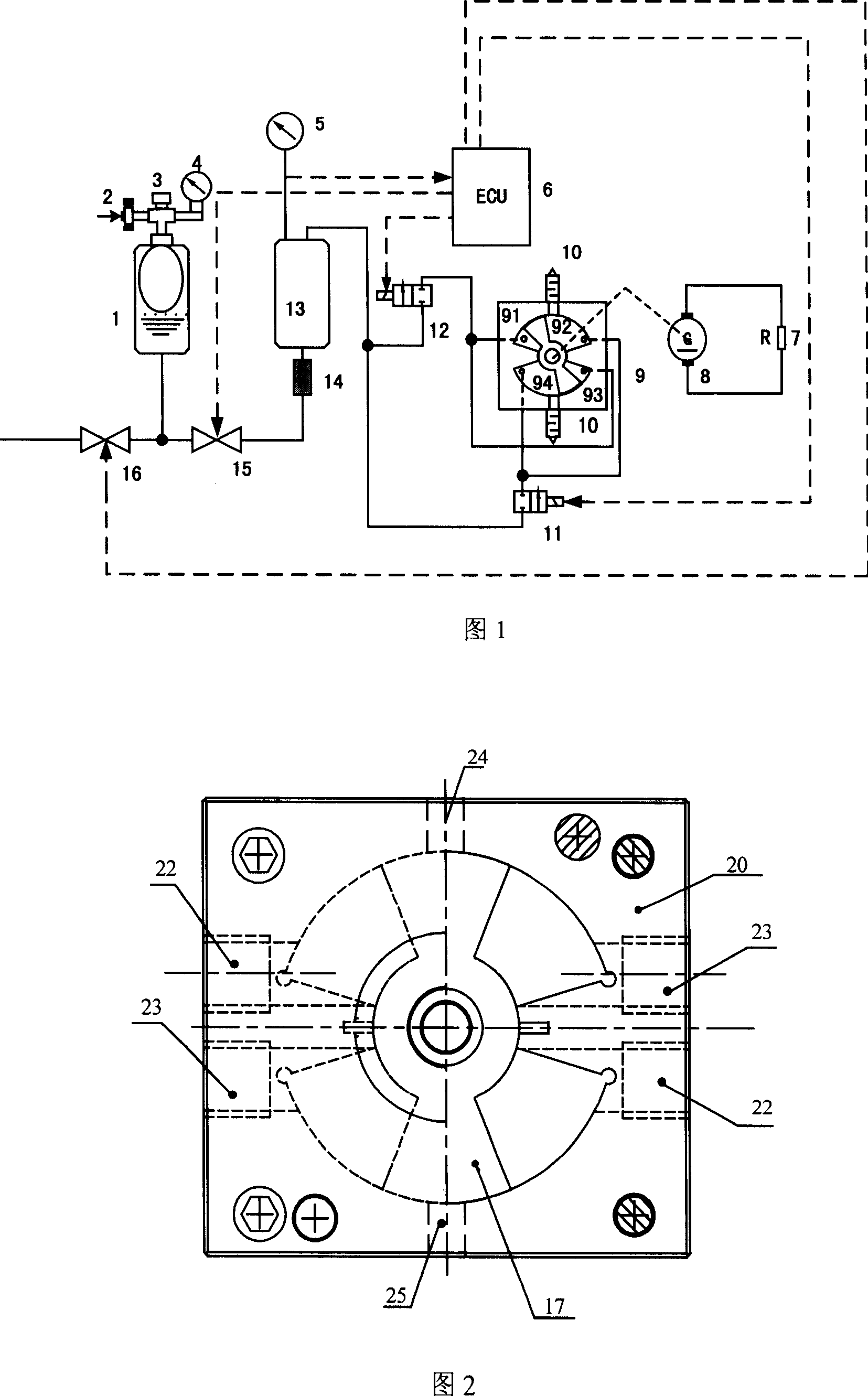
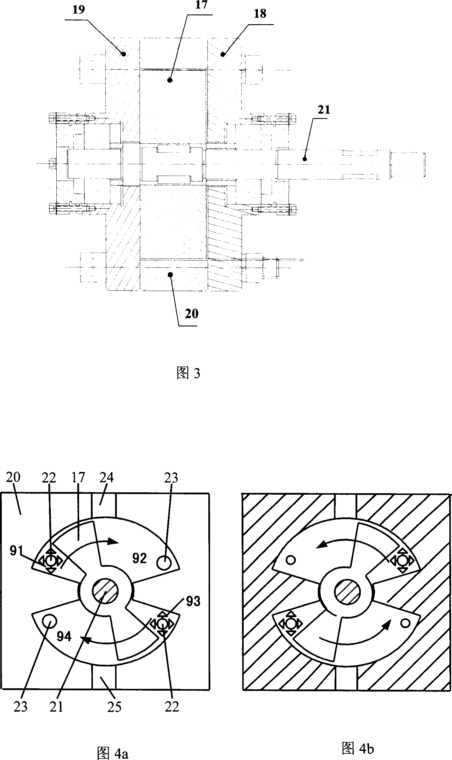
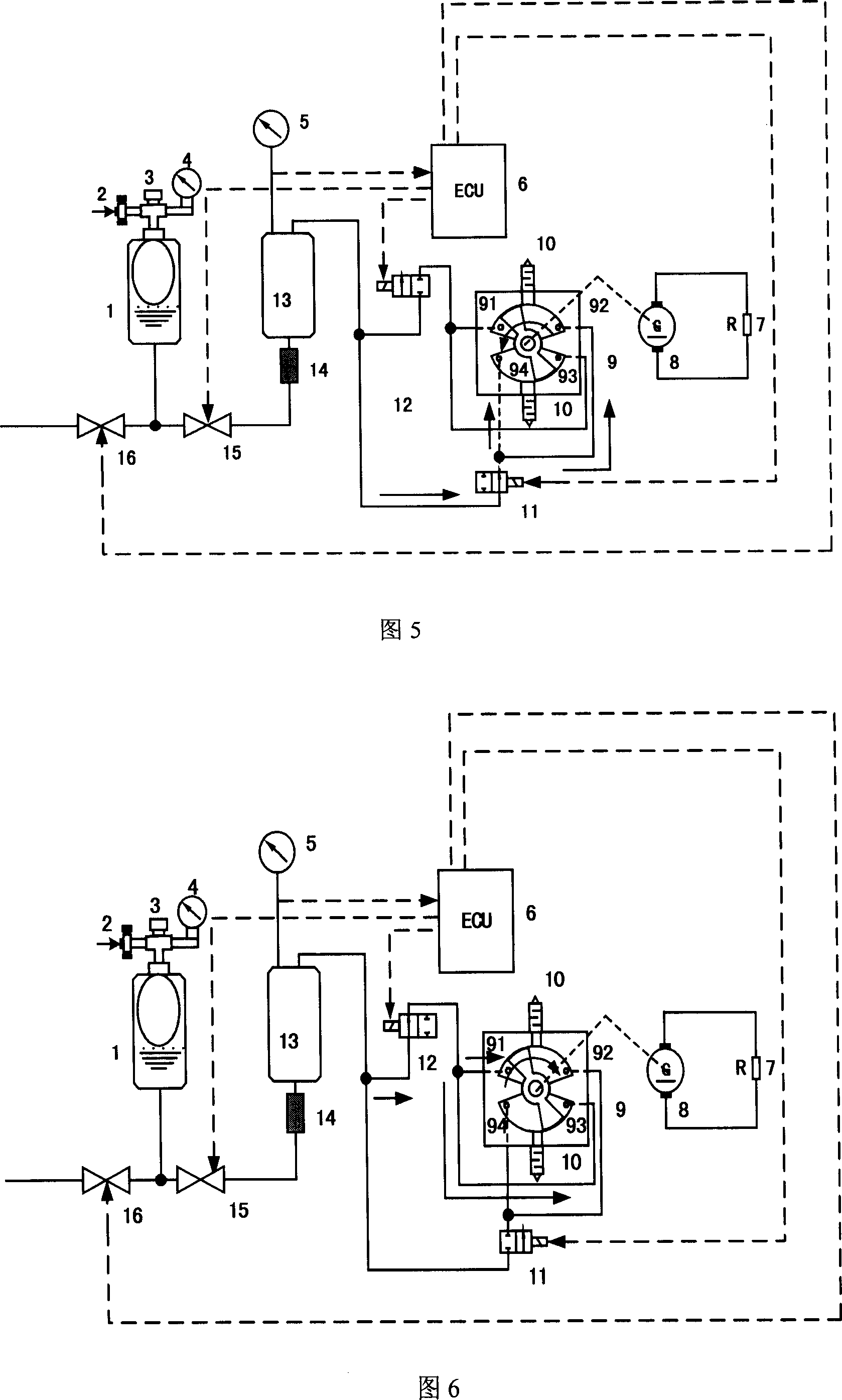
[0019] The pulse pendulum monocomponent engine of the present invention uses a monocomponent propellant such as a mixture of high-concentration hydrogen peroxide and diesel oil as fuel, and decomposes the above-mentioned mixed monocomponent fuel into high-temperature and high-pressure mixed gas through a catalytic reaction and stores it in the gas storage In the tank; when the pressure of the mixed gas in the gas storage tank reaches the set pressure value, the electronic control unit (ECU) controls the engine to work through two pneumatic switch valves, so as to realize the direct output of the swing power or the electric energy output through the generator. The operating frequency of the pendulum engine is equal to the switching frequency of the two pneumatic switching valves. The invention has the characteristics of small volume, light weight, high energy density, few moving parts, reliable operation and wide application range, etc. A power supply device ranging from watts ...


PUM


Abstract

The invention relates to a pulse swing single-unit engine, which comprises a single-unit fuel pot, a gas pot, a catalysis bed, an electric controller, a swing engine, a fuel control electromagnetic valve, and an emergence discharge valve. The invention uses the mixture of high-density hydrogen dioxide and diesel as the single-unit fuel, to be decomposed into high-temperature high-pressure mixture gas via catalysis decomposition to be stored in the gas pot. When the pressure of gas pot reaches preset value, the electric controller can use two aerated switches to start the engine to output swing power directly or output electricity via the generator, while the swing frequency is equal to the switch frequency of aerated valves. The invention has small volume, low weight, high energy density, and wide application, to be used to supply energy in non-oxygen condition or oxygen-lack condition.

Description

technical field [0001] The present invention relates to a single-component engine, in particular to an energy-autonomous robot, a portable electronic product or device for field work, and an oxygen-deprived or oxygen-deficient environment (such as space, underwater or plateau, etc.) Devices for direct or indirect use, belonging to the field of energy and power technology. Background technique [0002] Most micro-energy autonomous robots, micro-electromechanical systems or equipment, and portable electronic products for field operations require 1mW to 1000W energy and power supply devices. Generally speaking, the main energy supply devices in this power range are chemical batteries, fuel cells or small internal combustion generator sets. However, these energy or power supply devices have some disadvantages: the low energy density of chemical batteries makes it difficult to work for a long time; although fuel cells have higher energy density than chemical batteries, even with...

Claims


Application Information

Patent Timeline
Patent Type & Authority Applications(China)
IPC IPC(8): F01C9/00F01C13/00F01C20/00F01C21/10F01C21/18F01C21/00
Inventor 汪劲松夏必忠张辉郁鼎文刘学平段广洪毛乐山
Owner SHENZHEN GRADUATE SCHOOL TSINGHUA UNIV
Why Eureka
Try Eureka