
Electric device with nanowires comprising a phase change material

A technology of phase change materials and electrical devices, which is applied in the field of manufacturing electrical devices and can solve the problem of high switching energy

Inactive Publication Date: 2007-08-29
KONINKLIJKE PHILIPS ELECTRONICS NV
View PDF2 Cites 0 Cited by
  • Summary
  • Abstract
  • Description
  • Claims
  • Application Information

AI Technical Summary

Problems solved by technology

[0005] A disadvantage of the known production methods is that the energy required for switching between the amorphous and crystalline states, also called switching energy, is relatively high

Method used


Image

  • Electric device with nanowires comprising a phase change material
  • Electric device with nanowires comprising a phase change material
  • Electric device with nanowires comprising a phase change material

Examples


Embodiment Construction

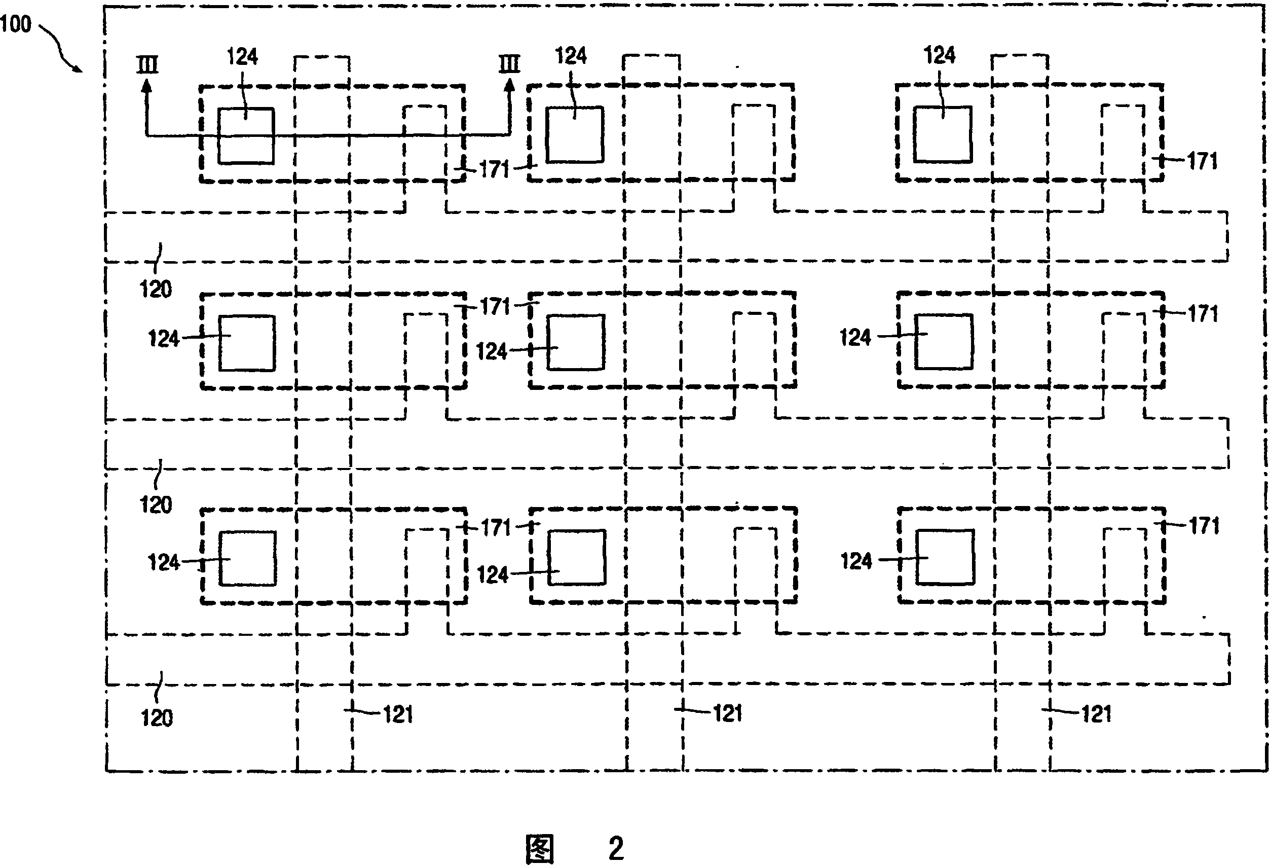
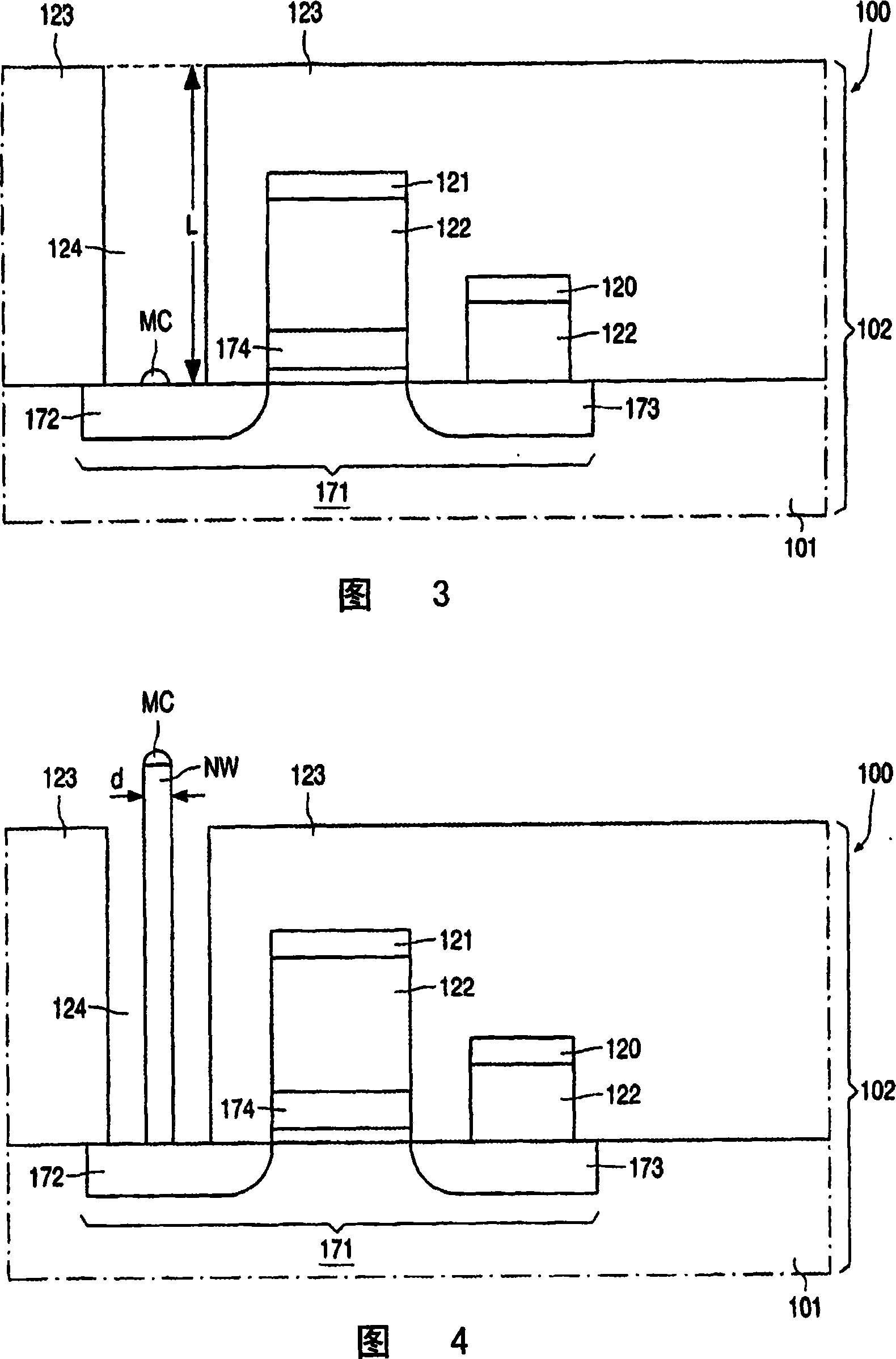
[0059] As shown in Figures 2-6 at different stages of fabrication, an embodiment of an electrical device 100 has a body 102 comprising a substrate 101 which may comprise, for example, a single crystal p-doped silicon semiconductor wafer. The body also includes an array of selection means 171 . In the embodiment shown in Figures 2-6, electrical device 100 has a 3x3 array, but the invention is neither limited to arrays of this size nor shape. The body 102 also comprises a grid of select lines 120 , 121 such that each memory cell is accessed via a respective select line 120 , 121 connected to a respective select means 171 .

[0060] In the embodiment shown in FIGS. 2-6 , the selection means 171 comprise Metal Oxide Semiconductor Field Effect Transistors (MOSFETs), more particularly NMOS transistors. The MOSFET has an n-doped source region 172 , an n-doped drain region 173 and a gate region 174 . Source region 172 and drain region 173 may include more than one portion of n-doped...


PUM

PropertyMeasurementUnit
Diameteraaaaaaaaaa

Abstract

The method according to the invention is directed to manufacturing an electric device (100) according to the invention, having a body (102) with a resistor comprising a phase change material being changeable between a first phase and a second phase, the resistor having a first electrical resistance when the phase change material is in the first phase, and a second electrical resistance different from the first electrical resistance when the phase change material is in the second phase. The resistor is a nanowire (NW) electrically connecting a first conductor (172, 120) and a second conductor (108, 121). The method comprises the step of providing a body (102) having the first conductor (172, 120), providing the first conductor (172, 120) with the nanowire (NW) thereby electrically connecting the nanowire (NW) and the first conductor (172, 120), and providing the nanowire (NW) with the second conductor (108, 121) thereby electrically connecting the nanowire (NW) and the second conductor (108, 121).

Description

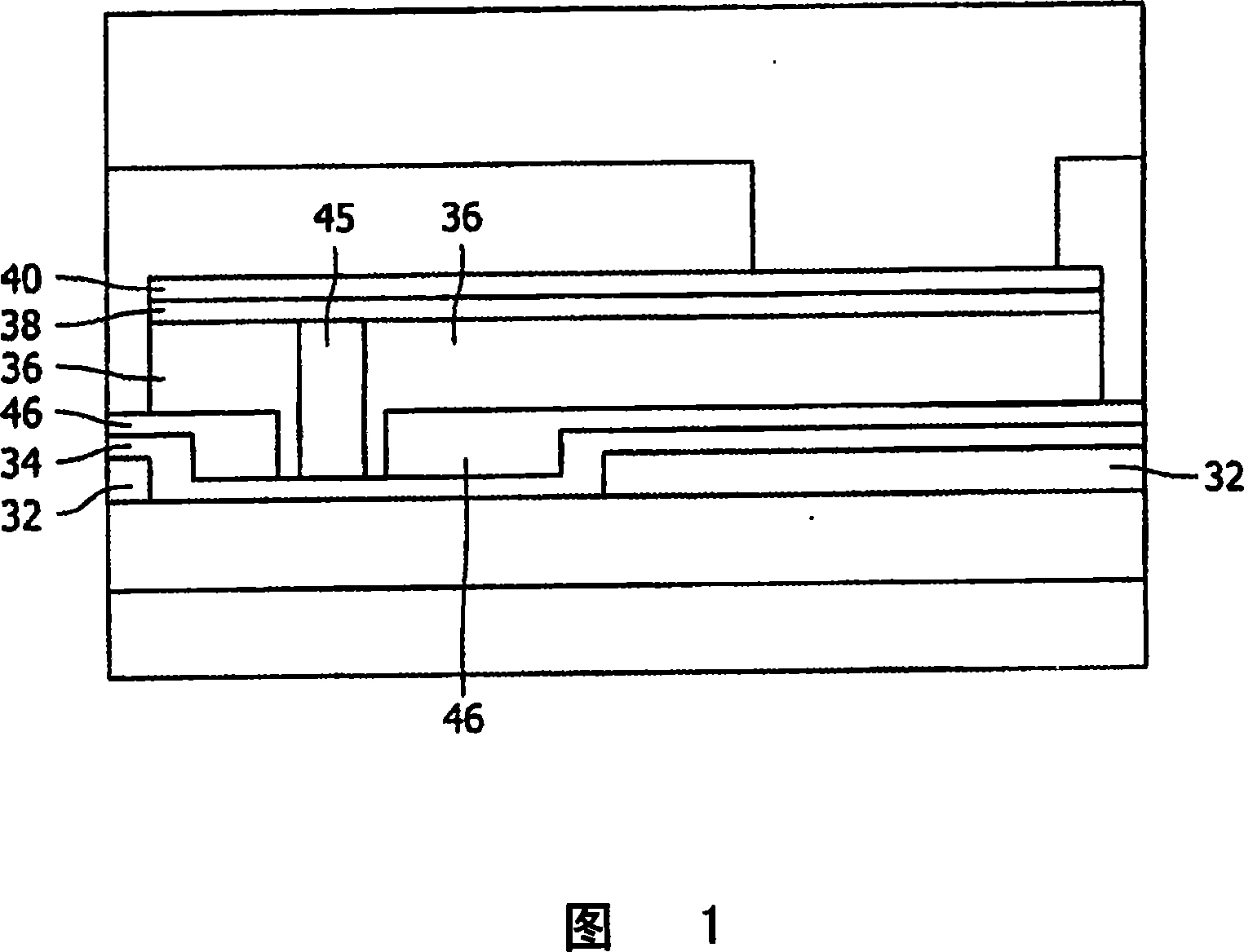
technical field [0001] The invention relates to a method of manufacturing an electrical device having a body with a resistor comprising a phase change material changeable between a first phase and a second phase, the resistor electrically connecting a first conductor and a second conductor. The resistor may have a first resistance when the phase change material is in the first phase and a second resistance different from the first resistance when the phase change material is in the second phase. [0002] The invention also relates to such an electrical device. Background technique [0003] US5933365 discloses a method in which a substrate is provided with an electrical contact layer 32 and an electrically conductive heating layer 34, both shown in Figure 1A. On top of these layers, air holes 46 are formed into the dielectric layer, thereby exposing the heating layer 34 . The dielectric layer and air holes are then provided with a memory material layer 36 of GeSbTe phase c...

Claims


Application Information

Patent Timeline
IPC IPC(8): H01L45/00H01L27/24
CPCH01L45/1233G11C13/0004H01L45/1625H01L45/06H01L45/148H01L27/2436H01L27/2481H01L27/2409B82Y10/00Y10S977/762G11C13/025H10B63/84H10B63/20H10B63/30H10N70/884H10N70/231H10N70/026H10N70/826H10N70/882
Inventor E·P·A·M·巴克斯M·H·R·兰克霍尔斯特
Owner KONINKLIJKE PHILIPS ELECTRONICS NV
Learn More