Consumable electrode surfacing method of electromagnetic complex field, and the device and extension application thereof

An electromagnetic composite and melting electrode technology is applied in the direction of non-electric welding equipment, arc welding equipment, resistance welding equipment, etc., which can solve the problems of low automation, difficult surfacing welding quality, and high labor intensity, so as to reduce sensitivity and change crystallization condition, effect of changing the solidification process

Inactive Publication Date: 2007-09-12
CHONGQING UNIV
View PDF3 Cites 44 Cited by
  • Summary
  • Abstract
  • Description
  • Claims
  • Application Information

AI Technical Summary

Problems solved by technology

[0005] At present, manual arc surfacing and flame surfacing are the most commonly used surfacing processes due to the advantages of the lowest cost, simplicity and flexibility, and la

Method used


Image

  • Consumable electrode surfacing method of electromagnetic complex field, and the device and extension application thereof
  • Consumable electrode surfacing method of electromagnetic complex field, and the device and extension application thereof
  • Consumable electrode surfacing method of electromagnetic complex field, and the device and extension application thereof

Examples


example 1

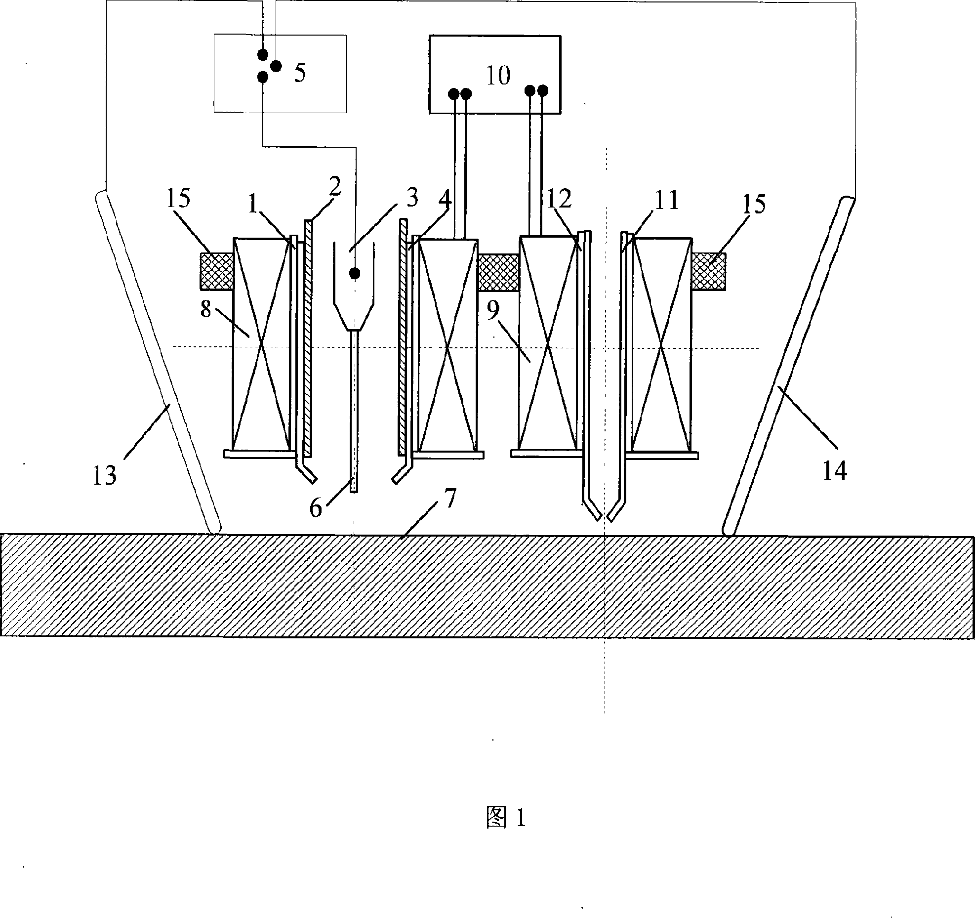
[0124] Example 1: When applying intermittent alternating longitudinal magnetic field to control carbon dioxide surfacing welding flux-cored wire Fe-Cr-Mn-W-V series high-carbon high-chromium alloy, the surfacing process parameters are as follows to obtain a good surfacing welding function layer: the excitation current of the electromagnetic stirring magnetic field is 3~20A, electromagnetic stirring magnetic field frequency 1~6Hz, welding current 100~200A, welding speed 0.3~0.8m / min, 100% carbon dioxide shielding gas 5~20L / min, wire feeding speed 3.5~0.8m / min.

example 2

[0125] Example 2: When an external electromagnetic composite field is applied to control MAG surfacing welding of Cr-W-Co hard alloys, the surfacing process parameters are as follows to obtain a good surfacing welding functional layer: the welding current is 120-180A, and the electromagnetic stirring magnetic field frequency is 1- 4Hz, auxiliary electric field strength current 10A ~ 40A, welding speed 0.3 ~ 1m / min. The intensity of the electromagnetic heat treatment magnetic field is 0.01T-0.2T, the frequency of the electromagnetic heat treatment magnetic field is 1-20Hz, and the flow rate of the protective gas (100% pure argon) is 5-20L / min.

example 3

[0126] Example 3: When the high-efficiency MAG surfacing welding of Fe-Ni-Cr-B-Si alloy is controlled by an external electromagnetic compound field, the surfacing welding process parameters are as follows to obtain a good surfacing welding functional layer: welding current is 350-700A, electromagnetic stirring magnetic field excitation current 5-30A, electromagnetic stirring magnetic field frequency 1-8Hz, auxiliary electric field strength current 5A-30A, welding speed 0.8-4m / min. The excitation current of the magnetic field for electromagnetic heat treatment is 15-40A, the frequency of the magnetic field for electromagnetic heat treatment is 1-25Hz, and the flow rate of protective gas (100% pure argon) is 20-30L / min.


PUM


Abstract

The present invention relates to one kind of composite electromagnetic field build-up welding method, apparatus and expanded application, and is composite electromagnetic field controlled gas protected build-up welding method. The welding apparatus is provided with exciting power source, exciting device, auxiliary electric field device and water cooling system. The exciting device has electromagnetic stirring exciting coil and electromagnetic heat treatment exciting coil; and the auxiliary electric field device includes one pair of movable electrodes. Through electromagnetic stirring, electromagnetic heat treatment and the compound effect of auxiliary electric field and the welding torch, the present invention realizes the build-up welding of alloy material in high efficiency, high quality and low cost.

Description

technical field [0001] The invention relates to the field of surface engineering surfacing welding, in particular to an electromagnetic composite field controlled powder core welding wire droplet jet transition melting electrode gas shielded surfacing welding method, equipment and expanded applications thereof. Background technique [0002] The metal gas shielded welding method characterized by the droplet rotating jet transfer is considered to be one of the efficient welding techniques. The similar technology widely used at home and abroad is a mixed gas melting electrode welding technology (such as TIME, RAPID MELT, LINFAST, etc.) with high helium as the main component. For my country, helium resources are relatively scarce and the cost is high. ; At the same time, the protective gas formula also has international intellectual property rights, making the use of its technology and equipment more expensive. At present, domestic researchers have adopted the method of external...

Claims


Application Information

Patent Timeline
IPC IPC(8): B23K31/02B23K37/00B23K9/04B23K9/173B23K9/08B23K9/095B23K35/30B23K35/38B23K26/34B23K11/00B23K20/12B23K9/18
Inventor 罗键
Owner CHONGQING UNIV
Why Eureka
Try Eureka