Liquid crystal display

A liquid crystal display and liquid crystal display panel technology, applied in the direction of instruments, nonlinear optics, optics, etc., can solve the problems that the brightness of the liquid crystal display cannot be enhanced, and the production is not easy to control, so as to reduce light loss, increase the utilization rate, and reduce costs burden effect

Active Publication Date: 2007-09-12
AU OPTRONICS CORP
View PDF1 Cites 5 Cited by
  • Summary
  • Abstract
  • Description
  • Claims
  • Application Information

AI Technical Summary

Problems solved by technology

However, the biggest difficulty of this method is that since the size of the microlens is below the micron level, and its surface structure is a curved surface structure, it is not easy to control in production.
Furthermore, due to the limited size and structure of the microlens, it is no longer possible to further enhance the brightness of the liquid crystal display by increasing the curvature of the curved surface structure of the microlens.

Method used


Image

  • Liquid crystal display
  • Liquid crystal display
  • Liquid crystal display

Examples


Embodiment Construction

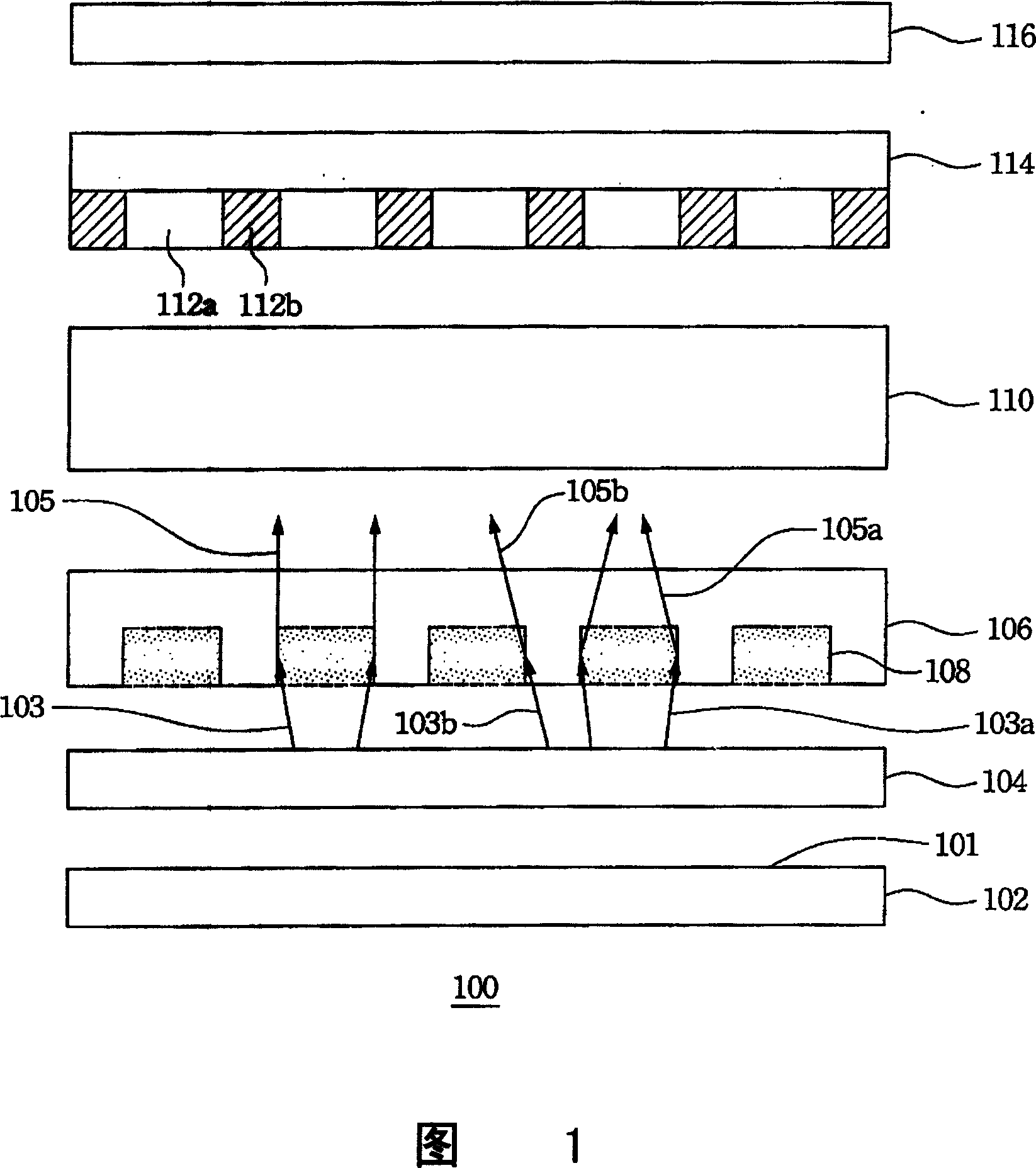
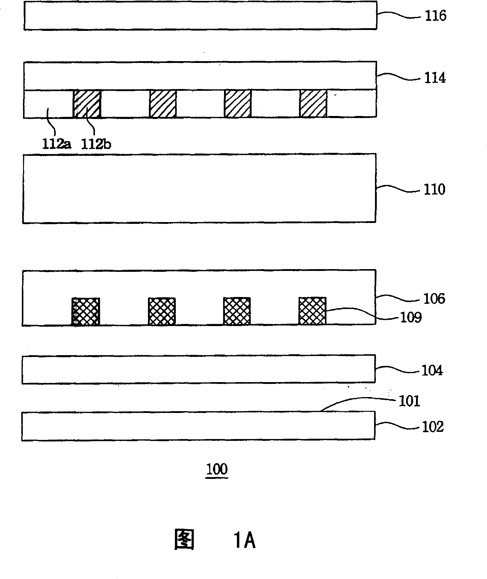
[0025] Please refer to FIG. 1 , which shows a schematic cross-sectional structure diagram of a liquid crystal display according to a preferred embodiment of the present invention. In FIG. 1 , the liquid crystal display 100 sequentially includes a backlight module 102 , a first polarizer 104 , a first transparent substrate 106 , a liquid crystal layer 110 , a second substrate 114 and a second polarizer 116 . The backlight module 102 includes a light emitting surface 101 . The first polarizer 104 is disposed on one side of the light emitting surface 101 of the backlight module 102 . A surface of the first transparent substrate 106 adjacent to the first polarizer 104 has a plurality of high refractive index regions 108 . The second substrate 114 is a color filter substrate, and the liquid crystal layer 110 is sandwiched between the first transparent substrate 106 and the second substrate 114 . The above-mentioned second substrate 114 further includes a light-transmitting region...


PUM

PropertyMeasurementUnit
thicknessaaaaaaaaaa
thicknessaaaaaaaaaa
refractive indexaaaaaaaaaa

Abstract

The invention is a high-brightness LCD, comprising in order: backlight module, high molecular film layer and LCD panel, where the high molecular film layer has multiple high-refractivity regions and multiple low-refractivity regions, staggered mutually; the LCD panel has multiple light transmitting regions located over the high-refractivity regions; when light penetrates through the high-refractivity regions to interfaces between high-refractivity and low-refractivity regions, reflection phenomena will occur on the interfaces so as to reflect the light into the light transmitting regions.

Description

【Technical field】 [0001] The present invention relates to a liquid crystal display, and in particular to a high-brightness liquid crystal display. 【Background technique】 [0002] In recent years, optoelectronic-related technologies have been continuously introduced, coupled with the arrival of the digital age, which has further promoted the vigorous development of the liquid crystal display market. Liquid Crystal Display (LCD) has the advantages of high image quality, small size, light weight, low voltage drive, low power consumption and wide application range, so it is widely used in portable TVs, mobile phones, notebooks, etc. Consumer electronics or computer products such as computers and desktop monitors are gradually replacing cathode ray tubes (Cathode Ray Tube; CRT) to become the mainstream of monitors. [0003] In view of the fact that the liquid crystal itself does not emit light, it is necessary to use a backlight module to supply the light source in order to achi...

Claims


Application Information

Patent Timeline
Patent Type & Authority Applications(China)
IPC IPC(8): G02F1/1335G02F1/1333
Inventor 吴佩勋蓝英哲王自豪李思汉刘耕儒
Owner AU OPTRONICS CORP
Why Eureka
Try Eureka