Method and equipment for producing transfer belt for image forming apparatus, and transfer belt for image forming apparatus

The technology of an imaging device and a manufacturing method is applied in the fields of manufacturing a transfer belt for an imaging device and the transfer belt for a device and an imaging device, and can solve the problems of difficulty in obtaining a surface layer with a small thickness and the like

Inactive Publication Date: 2007-09-12
SUMITOMO ELECTRIC FINE POLYMER INC
View PDF1 Cites 0 Cited by
  • Summary
  • Abstract
  • Description
  • Claims
  • Application Information

AI Technical Summary

Problems solved by technology

[0014] In addition, it is conceivable to install an extruded tubular shape surface layer on a molded body formed of a base layer and an elastic layer, but this method can only manufacture a transfer belt for an image forming apparatus with a small diameter (less than φ100 mm), and It is difficult to obtain a surface layer with a small thickness (less than 30μm)

Method used


Image

  • Method and equipment for producing transfer belt for image forming apparatus, and transfer belt for image forming apparatus
  • Method and equipment for producing transfer belt for image forming apparatus, and transfer belt for image forming apparatus
  • Method and equipment for producing transfer belt for image forming apparatus, and transfer belt for image forming apparatus

Examples


no. 1 approach

[0161] This embodiment is the insertion of a second composite layer, prepared by forming an elastomer layer on the outer surface of the bottom layer, into the inner side of the first composite body, the first composite layer being formed on the inner side of the surface layer. Prepared by forming an adhesive layer and using a core to bond the two layers.

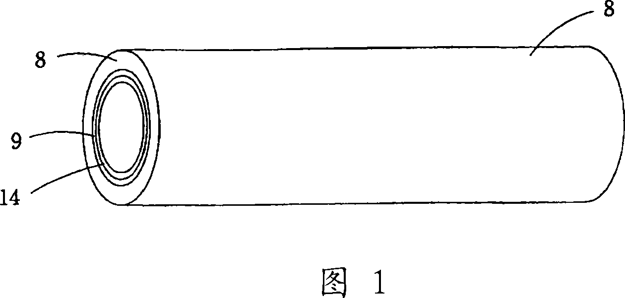
[0162] First, as shown in FIG. 1, PTFE (melting point: 327° C., thermal decomposition point: 400° C.) is coated on the inner surface of the steel outer pipe 8 by a dip coating method, and sintered at 380° C. to obtain a surface layer 9 , the steel outer tube 8 has a 1.76×10 -5 / °C coefficient of thermal expansion and has a mirror-polished inner surface.

[0163] Then, THV polymer (melting point: 120° C., thermal decomposition point: 400° C.) was dissolved in butyl acetate, a film was formed on surface layer 9 by dip coating, and dried to obtain adhesive layer 14 . The adhesive layer 14 is then heated at a temperature above...

no. 2 approach

[0174] This embodiment relates to a pressure-sensitive adhesive layer comprising a fluorine-containing polymer constituting the surface layer.

[0175] As shown in FIG. 1, PFA (350J dispersion, particle size 0.2 μm, manufactured by du Pont de Nemours & Co.) (melting point 295° C.) was coated by dip coating on the inner surface of the steel outer pipe 8, and the Sintering at 380°C to obtain the surface layer 9, the steel outer tube 8 has a 1.76×10 -5 / °C coefficient of thermal expansion, and has a mirror-polished inner surface.

[0176] Then, a THV polymer (THV220, manufactured by Sumitomo 3M Co.) (melting point: 120°C, thermal decomposition point: 400°C) was dissolved in butyl acetate to form a film on the surface layer 9 by dip coating, and dried, Thus, the adhesive layer 14 is obtained. The adhesive layer 14 is then heated at a temperature above the melting point of PFA and THV, ie 350° C., thereby causing it to adhere to the skin layer 9 . Others The method was carried o...

no. 3 approach

[0182] This embodiment also relates to an adhesive layer comprising a fluoropolymer constituting the surface layer.

[0183] In order to form the adhesive layer, powdery PFA (340J, particle size 0.2 μm, manufactured by du Pont de Nemours & Co.) for forming the skin layer was preliminarily added to the THV polymer in an amount of 60 parts with respect to 100 parts of THV polymer. (THV220, manufactured by Sumitomo 3M Co.), and THV polymer was dissolved in butyl acetate. Others The method was performed in the same manner as in the second embodiment, thereby obtaining a transfer belt for an image forming apparatus.

[0184] The thus-obtained transfer belt for image forming apparatus comprises: on a 60 μm thick base layer (polyimide), a 200 μm thick elastic layer (ionically conductive polyurethane), a 3 μm thick adhesive layer (THV) and a 5 μm thick (PFA), and a transfer belt for an image forming apparatus having excellent surface resistivity, toner release properties, and non-sta...


PUM

PropertyMeasurementUnit
thicknessaaaaaaaaaa
melting pointaaaaaaaaaa
particle sizeaaaaaaaaaa

Abstract

To provide a method for producing a transfer belt for image forming apparatus, having a large surface resistivity, excellent toner separation properties and noncontaminate properties, a stabilized volume resistivity, and the like, posing no problem of contaminant bleeding, and ensuring an excellent adhesion between a surface layer and an elastic layer, without causing thermal deformation or melting of the elastic layer; and to provide equipment for achieving that production process. [MEANS FOR SOLVING PROBLEMS] A first composite body is formed by providing a binder layer (14) of THV, or the like, on a surface layer (9) of PTFE or PFA, on the inner surface of an outer tube (8), a second composite body is formed by providing an elastic layer (12) of urethane, or the like, on a base layer (11) of PI, PAI, PVDF, or the like, and, after the second composite body is inserted into the outer tube and the outer tube is enlarged, the first composite body and the second composite body are thermally bonded.

Description

technical field [0001] The present invention relates to a manufacturing method and a manufacturing device for a transfer belt for an imaging device, and also to a transfer belt for an imaging device, and more particularly to a manufacturing method and a manufacturing device for a transfer belt for an imaging device. Used in a color image forming apparatus utilizing an electrophotographic process (such as a color copier or a color laser printer) for transferring a toner image (toner image) from a photosensitive drum (photosensitive drum) to a transfer material (paper) ; Also relates to a transfer belt for an image forming apparatus manufactured by such a manufacturing method or manufacturing apparatus. Background technique [0002] For an image transfer method in a color image forming apparatus such as a color copier or a color laser printer, a method of transferring a toner image formed on a photosensitive drum to a transfer material (paper) by means of a transfer belt for a...

Claims


Application Information

Patent Timeline
Patent Type & Authority Applications(China)
IPC IPC(8): B29D29/00B29K27/12B29C63/34B29K79/00G03G15/16
CPCB29C63/341G03G2215/0119B29D29/00G03G15/162B29C63/28B29C63/34G03G15/16
Inventor 池田一秋冈崎博志羽深正弘
Owner SUMITOMO ELECTRIC FINE POLYMER INC
Why Eureka
Try Eureka