Novel synchronous rectifying self-driven circuit for resonant reset forward converter

A forward converter and resonant reset technology, applied in the direction of DC power input conversion to DC power output, AC power input conversion to DC power output, instruments, etc., can solve the problem of increased driving loss and turn-on loss, increasing the difficulty of circuit design, Issues that affect the conversion efficiency of the whole module

Inactive Publication Date: 2007-09-19
FUZHOU UNIV
View PDF1 Cites 34 Cited by
  • Summary
  • Abstract
  • Description
  • Claims
  • Application Information

AI Technical Summary

Problems solved by technology

It can be seen that the driving voltage waveform of the freewheeling tube rises too slowly, and the driving loss and turn-on loss will greatly increase in the high-frequency module power supply, which will seriously affect the conversion efficiency of the whole module
The self-driving scheme of literature [2] is shown in Figure 2. Compared with the scheme of literature [1], it only adds a third winding drive, which solves the problem of driving the freewheeling tube S2 when the output voltage is too low or the output voltage is too high. Voltage problem, but there is also the problem of slow turn-on speed of S2 tube
Literature [3] uses the output voltage as the driving voltage of the freewheeling tube S2, which has a simple structure and low cost; but when the output voltage of the resonant reset forward converter circuit is lower than 5V or higher than 20V, the self-driving method in Literature [3] It is not suitable, because if the driving voltage is low, it will affect the switching performance and on-resistance of the MOS tube, and the current module power supply usually has the characteristics of low voltage and high current; when the output voltage is high, when the input voltage is in a wide range, Doing self-driving may damage the MOS tube, which limits the application of this self-driving method in engineering
The self-driving method of literature [4] is shown in Figure 4. The voltage on the output inductance is coupled as the drive voltage of the freewheeling tube. Compared with literature [3], there is no limit to the output voltage, but due to the large flow of the coupled inductance The current, so the drive circuit of S2 has a large power loss, and increases the difficulty of circuit design

Method used


Image

  • Novel synchronous rectifying self-driven circuit for resonant reset forward converter
  • Novel synchronous rectifying self-driven circuit for resonant reset forward converter
  • Novel synchronous rectifying self-driven circuit for resonant reset forward converter

Examples


Embodiment 1

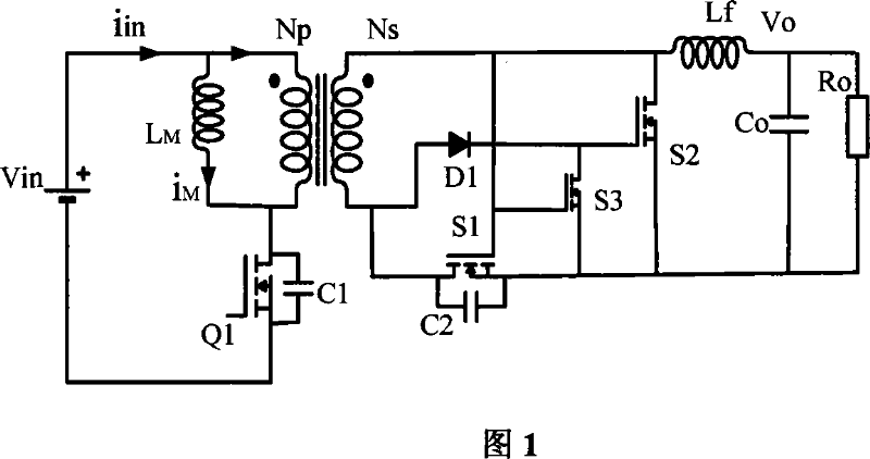
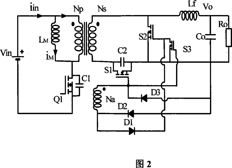
[0017] Embodiment 1: As shown in Figure 5, a new type of resonant reset forward converter, the main switch tube Q1, transformer Tr, resonant reset capacitors C1, C2, rectifier tube S1, freewheeling tube S2, control tube S3, the first Three auxiliary winding Na, auxiliary inductor La. The gate charging circuit of the synchronous freewheeling tube S2 is composed of an auxiliary inductor La, a diode D1, a freewheeling tube S2 and a diode D3. The B terminal of the auxiliary inductor is connected to the anode of the diode D1, the cathode of the diode D1 is connected to the gate of the freewheeling tube S2, the source of the freewheeling tube S2 is connected to the anode of the diode D3, and the cathode of the diode D3 is connected to the A terminal of the auxiliary inductor La. The gate discharge circuit of the synchronous freewheeling tube S2 is composed of a control tube S3, the gate of the control tube S3 is connected to the terminal with the same name of the third auxiliary win...


PUM


Abstract

The present invention provides a synchronization rectifying self-driving circuit for a new resonant reset forward converter. The gate charging loop of the freewheeling tube S2 comprises an auxiliary inductor La, diode D1 and D3. The gate charging loop of the freewheeling tube S2 is via a control tube S3. During the primary side main switch tube Q1 turn-on time, a third auxiliary winding charges the auxiliary inductor; after the primary side main switch tube Q1 is turned off, the auxiliary inductor La charges the gate capicitor of the freewheeling tube S2 with peak value current to turn on the capacitor by which switching loss and conducting loss of diode in the tube S2 caused by slowly turning on of the freewheeling tube S2 in the synchronization rectifying self-driving circuit for the resonant reset forward converter can be prevented. Thus the defect of slowly establishing of secondary side freewheeling tube driving voltage can be overcome and the common mode conduction time of the secondary side rectifying tube and freewheeling tube can be shorter compared with other self-driving manners, the turn-on performance of the freewheeling tube S2 is also better than external driving.

Description

Technical field: [0001] The invention relates to a novel synchronous rectification self-driving circuit of a forward converter with resonant reset. Background technique: [0002] In order to meet the development requirements of the future module power supply, it is indispensable to apply synchronous rectification technology in the resonant reset circuit. Compared with the external drive, the self-drive has advantages in cost and power density; but the secondary side of the resonant reset forward circuit The transformer waveform is a sine wave, and after the magnetic reset is completed, the voltage on the transformer is zero voltage for a period of time, and the secondary side presents a state of internal diode rectification, resulting in a large loss. Therefore, many self-driving schemes are correspondingly proposed [1], [2], [3], [4], which are respectively from the following documents: Document [1] from: [1] Karl T Fronk, Derry. Synchronous rectifierdrive mechanism for res...

Claims


Application Information

Patent Timeline
Patent Type & Authority Applications(China)
IPC IPC(8): H02M3/335H02M7/537H02M7/217
CPCY02B70/1475Y02B70/1441Y02B70/1433Y02B70/10
Inventor 华晓辉林维明
Owner FUZHOU UNIV
Why Eureka
Try Eureka