
Hard-coated antiglare film, method of manufacturing the same, optical device, polarizing plate, and image display

The technology of an image display device and manufacturing method is applied in the direction of optical elements, optics, polarizing elements, etc., which can solve the problems of not satisfactorily solving the hardness and anti-glare properties, being unable to exert anti-glare properties, and failing to obtain sufficient hardness, etc.

Inactive Publication Date: 2007-10-03
NITTO DENKO CORP
View PDF8 Cites 34 Cited by
  • Summary
  • Abstract
  • Description
  • Claims
  • Application Information

AI Technical Summary

Problems solved by technology

[0010] However, in these existing anti-glare hard-coated films, the problems of hardness and anti-glare properties have not been satisfactorily solved.
In Japanese Patent Laid-Open No. 11-286083, there is a problem that when the thickness of the above-mentioned hard coat layer is the above-mentioned level, sufficient hardness cannot be exhibited.
In Japanese Patent Laid-Open No. 2000-326447, there is a problem that if the above-mentioned structure is adopted, the surface roughness of the surface of the above-mentioned hard coat is completely ignored, and the above-mentioned inorganic fine particles are completely embedded in the inside of the above-mentioned hard coat. Composed of the case, can not exert sufficient anti-glare
The problem of the antireflection film described in JP-A-2001-194504 is that although the hardness and scratch resistance are improved, for example, particles with an average particle diameter of about 1.8 μm are added to a film thickness of about 20 μm. In the case of a hard coat layer, the particles are completely embedded in the hard coat layer and cannot exhibit sufficient anti-glare properties
The purpose of the antiglare antireflection film described in JP-A-2001-264508 is to improve scratch resistance, antiglare properties, etc., but the problem is that sufficient hardness cannot be obtained.

Method used

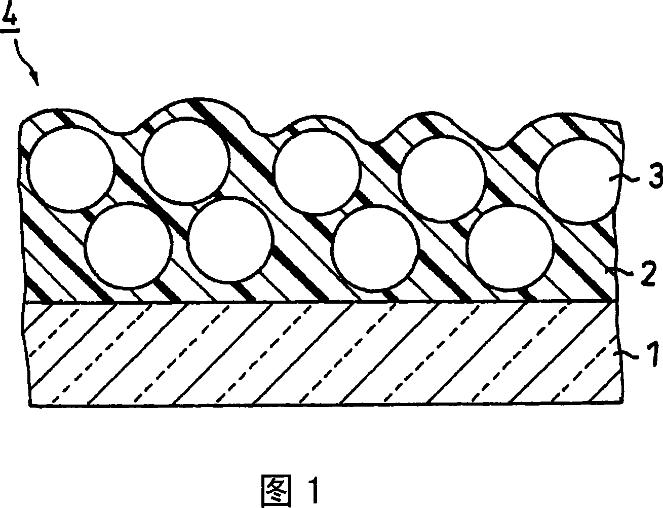
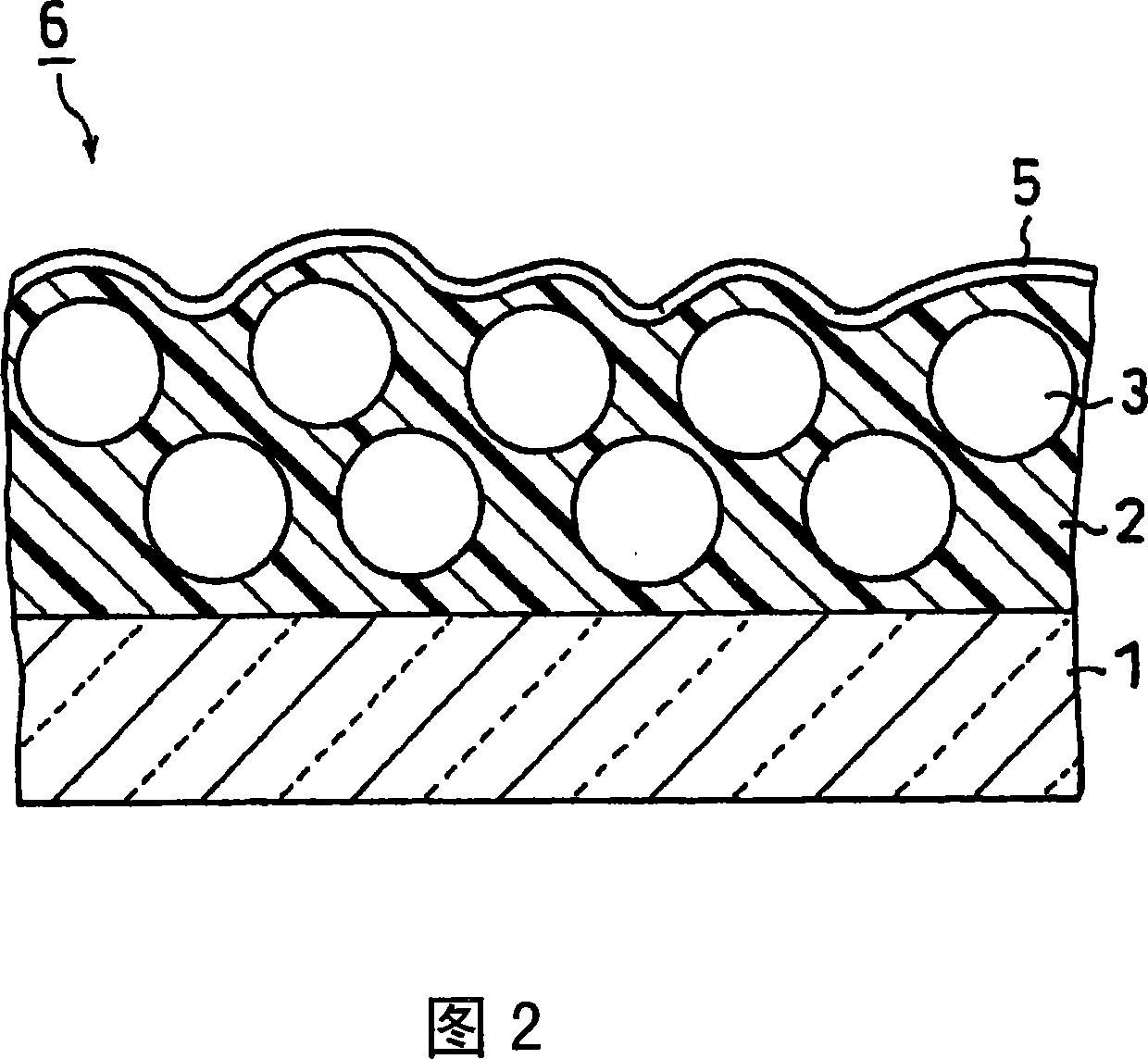
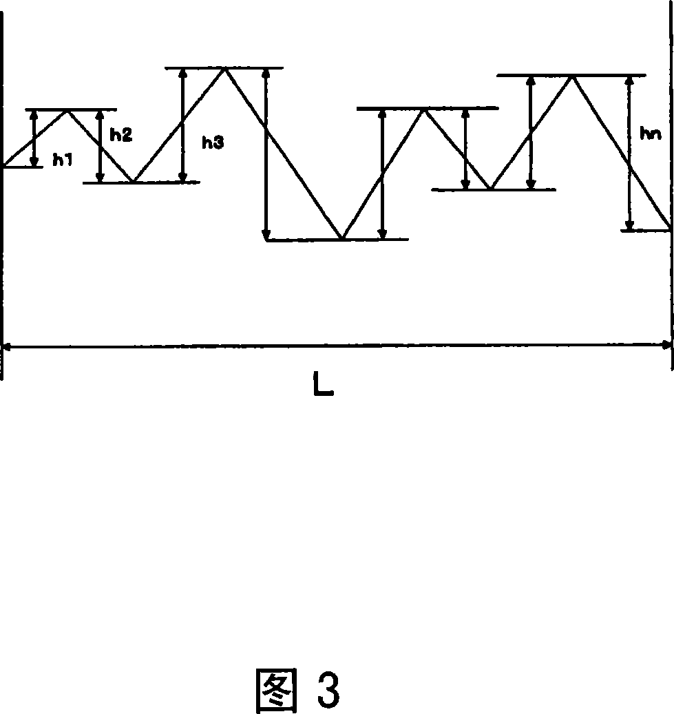

Image

  • Hard-coated antiglare film, method of manufacturing the same, optical device, polarizing plate, and image display
  • Hard-coated antiglare film, method of manufacturing the same, optical device, polarizing plate, and image display
  • Hard-coated antiglare film, method of manufacturing the same, optical device, polarizing plate, and image display

Examples


Embodiment 1

[0115] A resin raw material (manufactured by Dainippon Ink Co., Ltd., trade name: GRANDIC PC1071) was prepared. The resin raw material contained the following mixed solvent of ethyl acetate and butyl acetate at a solid content concentration of 66% by weight. (A) component, (B) component and (C) component, and the raw material of the resin component of the photopolymerization initiator. 30 parts by weight of PMMA particles (weight average particle diameter 10 μm, refractive index 1.49) and 0.5 parts by weight of a leveling agent were added to 100 parts by weight of the resin raw material. Then, the resin raw material that has added above-mentioned PMMA particle and leveling agent is diluted with ethyl acetate, so that butyl acetate: ethyl acetate (weight ratio)=55: 45 (the ethyl acetate ratio of relative total solvent is 45 weight %), and the solid content concentration was 55% by weight. Thus, the hard coat layer forming material was prepared. The above-mentioned leveling ag...

Embodiment 2

[0123] In this example, except that the addition amount of the PMMA particles was changed to 15 parts by weight, the same method as in Example 1 was used to produce an anti-glare hard-coated film.

Embodiment 3

[0125] In the present embodiment, 30 parts by weight of PMMA particles (refractive index: 1.49) with a weight average particle diameter of 15 μm are added, and the solid content concentration is changed to 35%. In addition, the same method as in Example 1 is adopted, Production of anti-glare hard-coated films.


PUM

PropertyMeasurementUnit
Thicknessaaaaaaaaaa
Mean tilt angleaaaaaaaaaa
Film thicknessaaaaaaaaaa

Abstract

A hard-coated antiglare film is provided that has high hardness, high scratch resistance, and good antiglare properties. In the hard-coated antiglare film of the present invention including a transparent plastic film substrate, a hard-coating layer containing fine particles is formed on at least one surface of the transparent plastic film substrate, the hard-coating layer has a thickness in the range of 15 to 30 mum, the fine particles have a weight average particle size of 30 to 75% of a thickness of the hard-coating layer, the average tilt angle thetaa of the unevenness of the hard-coating layer surface is in the range of 0.4 DEG to 1.5 DEG , and the hard-coating layer is formed using a resin for forming the hard-coating layer containing three specific resin components.

Description

technical field [0001] The invention relates to an anti-glare hard-coated film, a manufacturing method of the anti-glare hard-coated film, an optical element, a polarizer and an image display device. Background technique [0002] In recent years, with the advancement of technology, on the basis of the existing CRT (Cathode Ray Tube), liquid crystal displays (LCDs), plasma displays (PDPs) and electroluminescent displays (ELDs) have also been developed and put into practical use. change. Among them, as far as LCD is concerned, along with technological innovations related to high field of view, high definition, high-speed response, color reproduction, etc., applications using LCD are also changing from notebook personal computers or monitors to TVs. . The basic structure of an LCD is that flat glass substrates each equipped with transparent electrodes are arranged to face each other through a spacer so as to form a gap with a certain interval, and a liquid crystal material is...

Claims


Application Information

Patent Timeline
IPC IPC(8): G02B1/11G02B5/30B32B27/06B32B33/00G02B1/111G02B1/14
Inventor 鹰尾宽行滨本大介高田胜则楠本诚一木村雄一重松崇之
Owner NITTO DENKO CORP
Learn More