Steel pipe for air bag inflator and method for production thereof

A manufacturing method and inflator technology, applied in the direction of manufacturing tools, furnace types, furnaces, etc., can solve the problems of lack of high strength and toughness, and achieve the effects of excellent low temperature toughness, improved fuel cost, and high dimensional accuracy

Active Publication Date: 2007-10-03
NIPPON STEEL CORP
View PDF4 Cites 16 Cited by
  • Summary
  • Abstract
  • Description
  • Claims
  • Application Information

AI Technical Summary

Problems solved by technology

However, although the technologies described in the above-mentioned publications all intend to obtain high-strength and high-toughness steel pipes for air bags, the achieved tensile strength is 800 MPa or more and less than 900 MPa, or 900 MPa or more and less than 1000 MPa, and even the highest is 947 MPa. , but did not achieve high strength and excellent toughness above 1000MPa at the same time

Method used


Image

  • Steel pipe for air bag inflator and method for production thereof
  • Steel pipe for air bag inflator and method for production thereof
  • Steel pipe for air bag inflator and method for production thereof

Examples


Embodiment 1

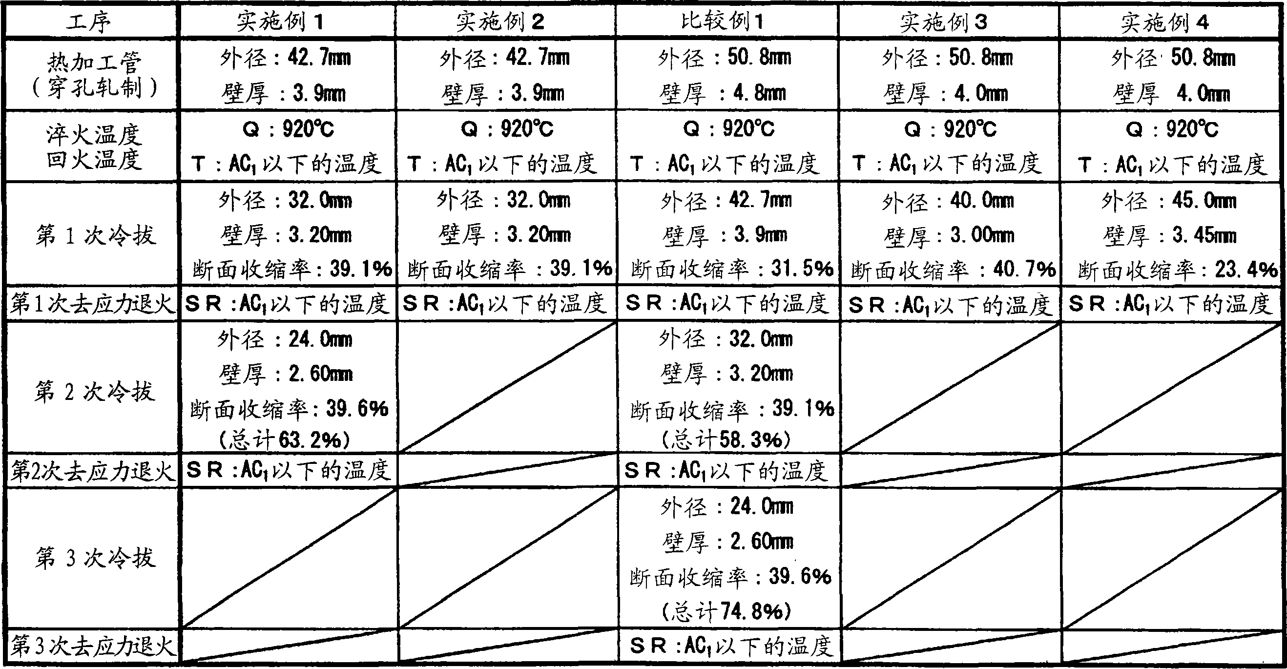
[0087] Using a steel billet having the steel composition shown in Table 1, after heating to 1250°C, it is pierced and rolled by the usual Mannesmann piercing mill-mandrel mill method, thereby hot-working the steel pipe to the outer diameter The nominal size of 42.7mm × wall thickness 3.9mm is used to manufacture seamless steel pipes as tube blanks. Among the steel compositions shown in Table 1, the values ​​of Nos. 17 to 19 (Mn+40×Ti) are examples out of the range specified by the present invention, and Nos. 20 and 21 are examples in which the Cr content is out of the range. These They are all steel.

[0088] As shown in Table 2, after heating each tube billet with a common walking heating furnace (the temperature rise rate is 0.3°C / sec, and the atmosphere is the atmosphere) for 10 minutes to 920°C, water-cooled water quenching (in Table 2 is used Q represents the heating temperature), then use a walking furnace (the atmosphere is the atmosphere) in the Ac 1 Tempering was pe...

Embodiment 2

[0090] Although steel pipes were produced in the same manner as in Example 1, as shown in Table 2, the second drawing out of the two cold drawing performed in Example 1 and the subsequent stress relief annealing were not performed. Therefore, the section reduction rate of cold drawing is 39.1%, and the final shape of the steel pipe is: the outer diameter is 32.0mm, and the wall thickness is 3.20mm.

Embodiment 3

[0094] Although steel pipes were produced in the same manner as in Example 1, the shape of the blank pipe was 50.8 mm in outer diameter and 4.0 mm in thickness. After heat-treating the blank tube by the same quenching and tempering as in Example 1, as shown in Table 2, cold drawing was performed once with a reduction in area of ​​40.7%, and then performed in the same manner as in Example 1. stress relief annealing. The final shape of the steel pipe is: outer diameter 40.0mm, wall thickness 3.00mm.


PUM

PropertyMeasurementUnit
tensile strengthaaaaaaaaaa

Abstract

A steel pipe for an air bag inflator which has a high strength of a tensile strength of 900 MPa or more, preferably 1000 MPa or more, together with high toughness, and exhibits good burst resistance wherein no cracks develop in a burst test at -40 DEG C or lower is produced by a method comprising providing a raw steel pipe containing, in mass %, 0.05 to 0.20 % of C, 0.1 to 1.0 % of Si, 0.025 % or lower of P, 0.010 % or lower of S, 0.05 to 1.45 % of Cr, 0.10 % or less of Al, 0.02 % or less of Ti, and one or both of Ti and Mn satisfying 0.4 = Mn + 40 X Ti = 1.2, rapidly cooling the raw steel pipe from a temperature of Ac1 transformation temperature or higher, tempering the resultant steel pipe at a temperature lower than Ac1 transformation temperature, subjecting the tempered steel pipe to a cold working wherein a reduction of area is 65 % or less, and then subjecting the worked steel pipe to a stress relief annealing at a temperature lower than Ac1 transformation temperature. The L/T ratio of X ray integral intensity ratios of {110} face measured in the cross section perpendicular to the axis direction (L) and the cross section perpendicular to the periphery direction (T) of the above steel pipe is 50 or lass.

Description

technical field [0001] The present invention relates to steel pipes for airbag inflators (steel pipes for airbag inflators) having both high strength such as a tensile strength of 900 MPa or more, preferably 1000 MPa or more, and a steel pipe for airbag inflators preferably at -40°C. There is no brittle fracture surface at -60°C, and no cracks develop in the static pressure rupture test under such low temperature conditions. Such good toughness and low temperature crack resistance. Background technique [0002] In order to increase the safety of the car, the airbag (air cushion) system installed on the driver's seat and the passenger's seat has become a standard configuration. Previous airbag systems used explosive chemicals to generate the gas used to deploy the airbag. However, other types of airbag systems that fill steel pipes called inflators (or air reservoirs) with high-pressure gas for airbag deployment have been developed and used widely in response to the need to ...

Claims


Application Information

Patent Timeline
Patent Type & Authority Applications(China)
IPC IPC(8): C22C38/00C21D9/08C21D8/10C22C38/54B60R21/26
CPCB60R2021/26082C21D1/18C21D1/30C21D8/10C21D9/14C22C38/02C22C38/04C22C38/18C22C38/28
Inventor 高野孝司荒井勇次近藤邦夫一入启介
Owner NIPPON STEEL CORP
Why Eureka
Try Eureka