Structure for packing light-emitting diodes, light-conducting pipe and liquid crystal display device thereof

A technology of liquid crystal display devices and light-emitting diodes, which is applied in the field of liquid crystal display devices and backlight modules, and can solve problems such as not being environmentally friendly, reducing the practicability of backlight module liquid crystal display devices, and environmental pollution.

Active Publication Date: 2007-11-21
INNOLUX CORP
View PDF0 Cites 41 Cited by
  • Summary
  • Abstract
  • Description
  • Claims
  • Application Information

AI Technical Summary

Problems solved by technology

[0003] However, since cold cathode fluorescent lamps or hot cathode fluorescent lamps contain harmful substances such as mercury, it is not easy to recycle resources after long-term use, and it is easy to cause environmental pollution
In addition, with the rising awareness of global environmental protection and the trend of modern people's emphasis on recycling electronic products, backlight modules that use mercury-containing cold-cathode fluorescent tubes or hot-cathode fluorescent tubes as light sources, would appear to be quite unfriendly to the environment
As a result, the practicability of the backlight module and the liquid crystal display device will be greatly reduced.

Method used


Image

  • Structure for packing light-emitting diodes, light-conducting pipe and liquid crystal display device thereof
  • Structure for packing light-emitting diodes, light-conducting pipe and liquid crystal display device thereof
  • Structure for packing light-emitting diodes, light-conducting pipe and liquid crystal display device thereof

Examples


Embodiment 1

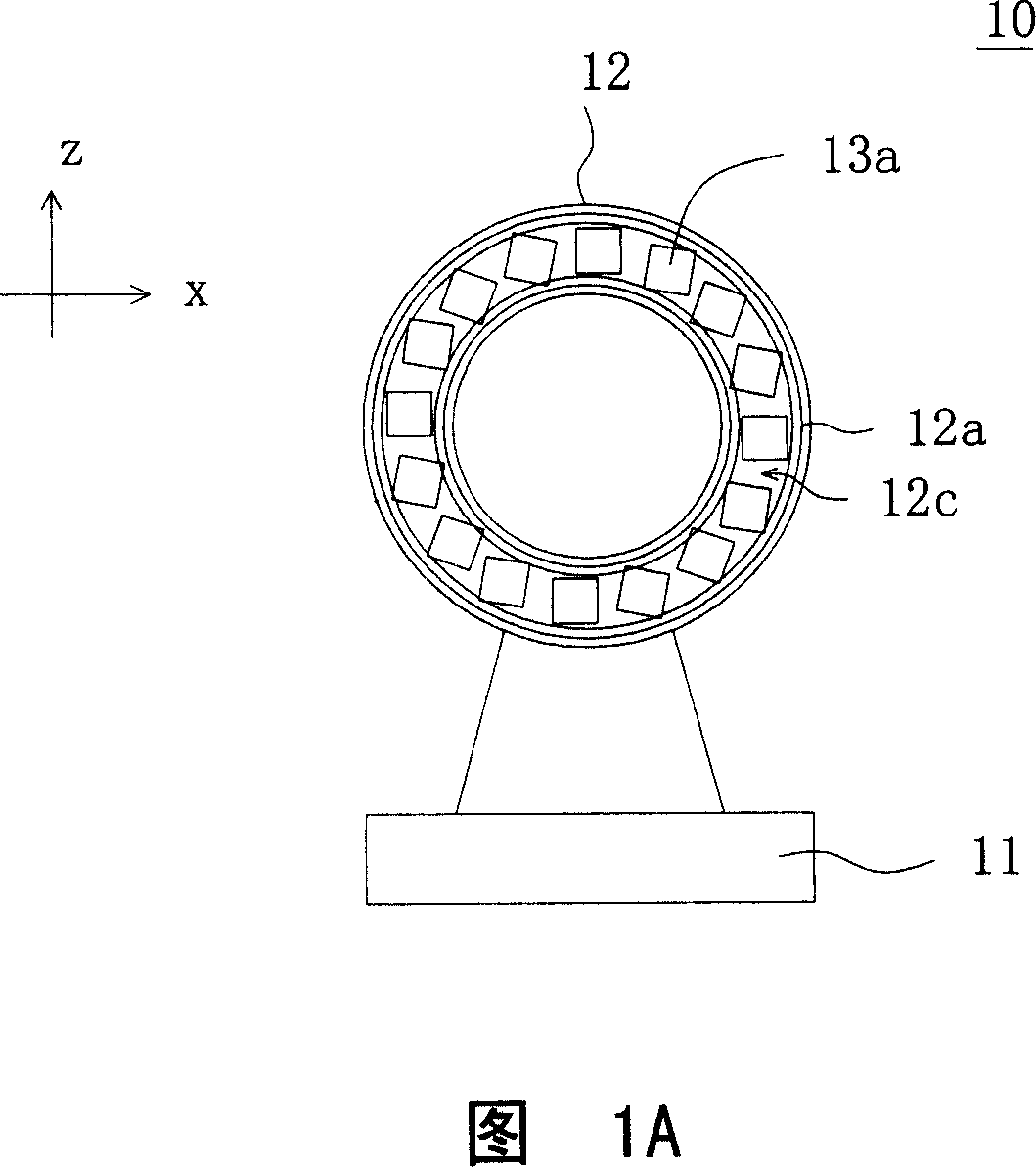
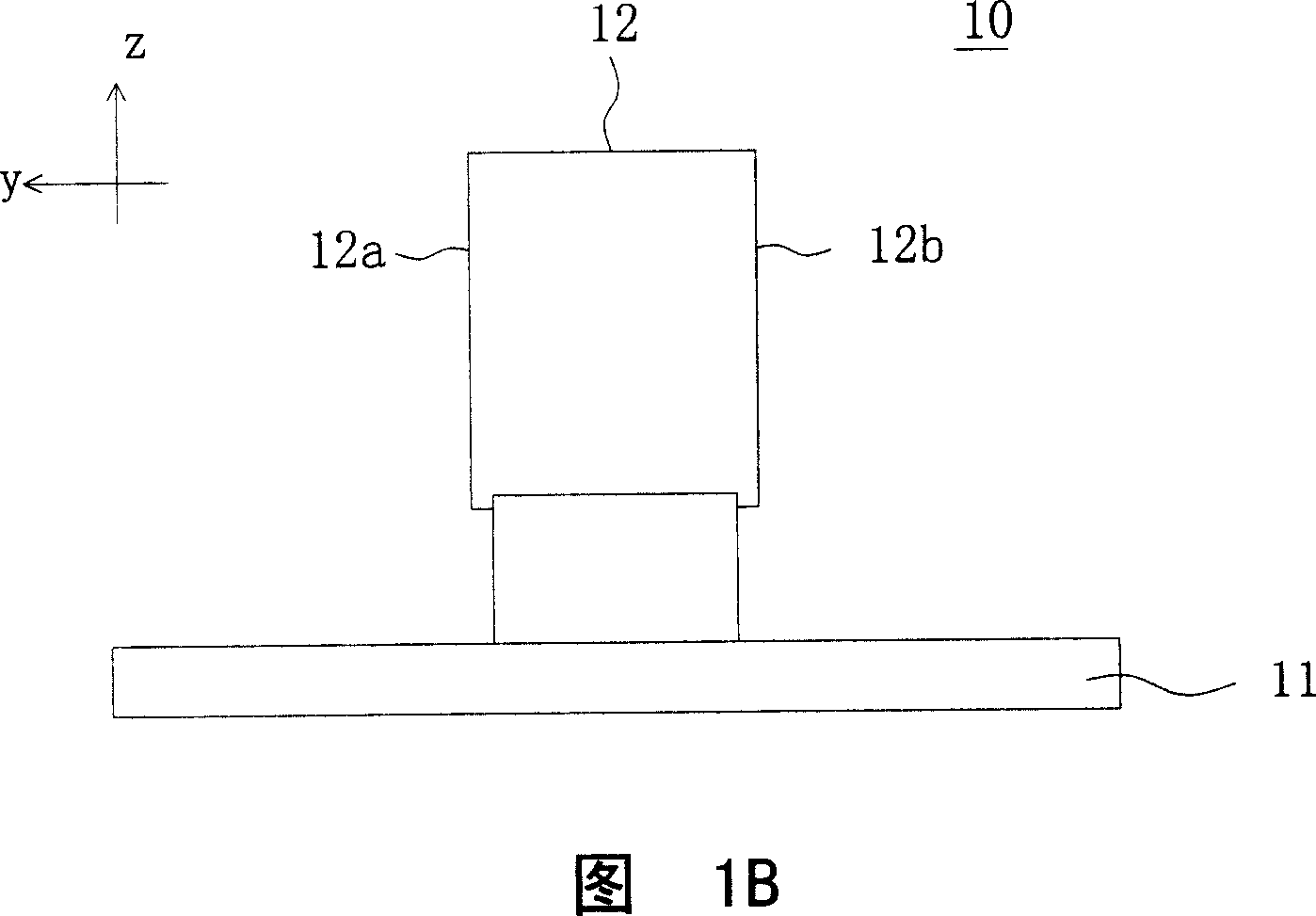
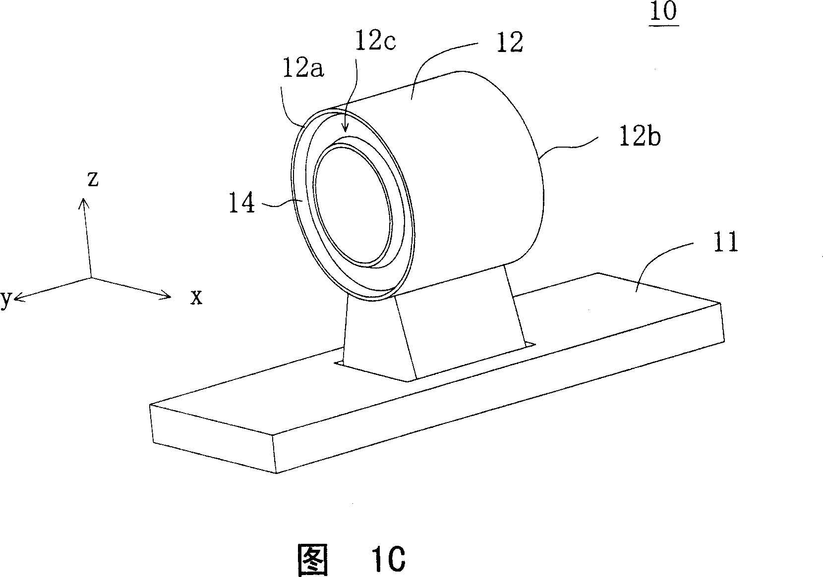
[0074] Please refer to FIGS. 1A-1E at the same time. FIG. 1A shows a front view of the LED packaging structure according to Embodiment 1 of the present invention, and FIG. 1B shows a side view of the LED packaging structure of FIG. 1A . Fig. 1C shows a perspective view of the base and body of the light emitting diode package structure of Fig. 1A, Fig. 1D shows a front view of the state when the light emitting diode structure of Fig. 1A also includes phosphor powder and colloid, and Fig. The diode structure also includes the back view of the state of the phosphor and colloid.

[0075] As shown in FIGS. 1A-1B , the LED packaging structure 10 includes a base 11 , a body 12 and a plurality of first LED chips 13 a. The body 12 is disposed on the base 11, and has a first side 12a, and the first side 12a has a groove 12c surrounding an edge. The first LED chip 13 a is disposed on the bottom of the first edge-surrounding groove 12 c for providing single side light of the LED package ...

Embodiment 2

[0081] Please refer to FIGS. 2A-2C at the same time. FIG. 2A shows a perspective view of a light guide according to Embodiment 2 of the present invention. Fig. 2B shows a sectional view of the light pipe viewed from the +x direction with the yz plane of Fig. 2A as the sectional plane, and Fig. 2C shows a sectional view with the xz plane of Fig. 2A as the sectional plane and from the +y direction An enlarged cross-sectional view of the light pipe looking into the light pipe. As shown in FIGS. 2A-2C , the light guide pipe 20a is used to receive light from a light source at least at one end thereof and perform light interference. The light pipe 20a includes a cylinder 21 and several prism structures 22a. The cylinder 21 has an outer peripheral side 21a and an inner reflective surface 21b, and the inner reflective surface 21b is used for reflecting the light received by the light pipe 20a. The prism structure 22a is disposed between the outer peripheral side 21a and the inner re...

Embodiment 3

[0088] Please refer to FIG. 3 , which shows a cross-sectional view of a light guide according to Embodiment 3 of the present invention. The difference between the light guide pipe 20b of the present embodiment and the light guide pipe 20a of the second embodiment lies in the prism structure 22b, as for the other same constituent elements, the reference numerals continue to be used and will not be repeated here.

[0089]As shown in FIG. 3, although the prism structure 22b of the present embodiment and the prism structure 22a of the second embodiment are both dots, the dots of the present embodiment are pits, that is, the prism structure 22b is a pit. As for the formation method of the light guide pipe 20b, it is substantially the same as the formation method of the light guide pipe 20a in the second embodiment, and will not be repeated here. In addition, the distribution and formation of the prism structures 22b are substantially the same as the distribution and formation of th...


PUM


Abstract

A LBD packing structure includes a base, noumenon and several LBD. The noumenon is installed on the base with a circle groove on one side. LBD are fixed in the groove to supply a lateral light for the packing structure. The invention also provides an optical pipe which includes a column and several prisms. The column is of an outer side and an inner reflecting side. The prisms are installed in between the outer and inner sides. By combining the LBD package and the optical pipe, the package is capable of generating diffusion light and be used in apheliotropic module and LCD displayer.

Description

technical field [0001] The present invention relates to a backlight module and a liquid crystal display device using the backlight module, in particular to a light-emitting diode packaging structure capable of emitting light sideways and a light guide tube that can guide ring-shaped light into light similar to a lamp tube And a backlight module and a liquid crystal display device using the light pipe. Background technique [0002] With the rapid progress of liquid crystal display device manufacturing technology, and its advantages of thinness, power saving and no radiation, liquid crystal displays are widely used in personal digital assistants (personal digital assistants, PDAs), notebook computers, digital cameras, digital In various electronic products such as cameras, mobile phones, computer screens and LCD TVs. Coupled with the industry's active investment in research and development and the adoption of large-scale production equipment, the quality of liquid crystal dis...

Claims


Application Information

Patent Timeline
Patent Type & Authority Applications(China)
IPC IPC(8): H01L25/00H01L25/075G02B6/00G02F1/13357G02F1/133F21S4/00F21Y115/10G02F1/1335
Inventor 洪振滨
Owner INNOLUX CORP
Why Eureka
Try Eureka