Method for fabricating field emitter electrode using array of carbon nanotubes

A technology of emitting electrodes and carbon nanotubes, applied in the direction of oriented carbon nanotubes, discharge tube/lamp manufacturing, nanotechnology, etc., can solve insurmountable problems

Active Publication Date: 2010-04-14
KOREA ADVANCED INST OF SCI & TECH
View PDF4 Cites 1 Cited by
  • Summary
  • Abstract
  • Description
  • Claims
  • Application Information

AI Technical Summary

Problems solved by technology

However, this method also fails to align the carbon nanotubes at high density in large areas in the direction that generates the electromagnetic field, and does not overcome the drawbacks of having to burn the polymer during the fabrication process.

Method used


Image

  • Method for fabricating field emitter electrode using array of carbon nanotubes
  • Method for fabricating field emitter electrode using array of carbon nanotubes
  • Method for fabricating field emitter electrode using array of carbon nanotubes

Examples


Embodiment 1

[0053] Embodiment 1: Preparation of carbon nanotubes

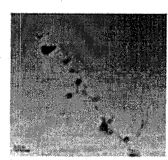
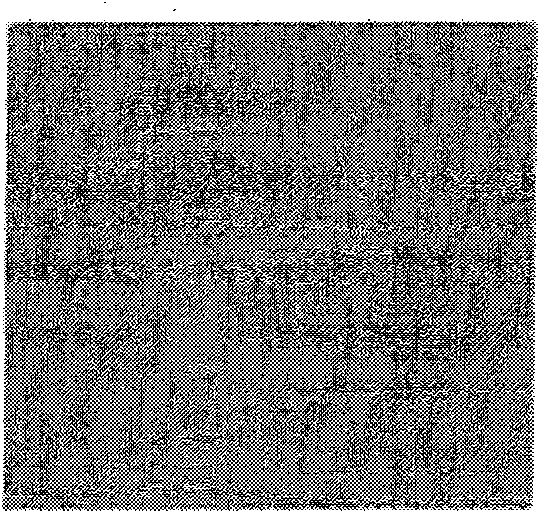
[0054] 500 mg of carbon nanotubes were placed in a furnace at 365° C., where they were heat-treated for 90 minutes while 0.1 SLM (standard liter per minute) of air was injected into the furnace. The heat-treated carbon nanotubes were added to 500 ml of hydrochloric acid, sonicated for 1 hour, and filtered through a filter. Afterwards, the filtered carbon nanotubes were added to 500 ml of hydrochloric acid, sonicated for 1 hour, and filtered through a 1-μm filter. Repeat the hydrochloric acid treatment process 3-5 times to purify the carbon nanotubes. Also, pictures by a transmission electron microscope (TEM) show carbon nanotubes before and after the purification treatment (see FIG. 2 ). As a result, as shown in Figure 2, the carbon nanotubes contained impurities before purification (see Figure 2a ), while after purification they are free of impurities (see Figure 2b ). The purified carbon nanotubes were immersed ...

Embodiment 2

[0055] Example 2: Binding Magnetic Particles to Carbon Nanotubes

[0056] 10.8g of ferric chloride (FeCl 3 ·6H 2 O) and 36.5 g of sodium oleate (Cl 8 h 33 NaO 2 ) was added to a mixture of 80 ml of ethanol, 60 ml of distilled water and 140 ml of hexane, and heated at 70° C. for 4 hours, thereby preparing an iron oleate complex. 12 g of the prepared iron oleate complex, 2.83 g of oleic acid, and 3 ml of dimethylformamide (DMF) solvent were mixed with each other, and 150 mg of the carbon nanotubes prepared in Example 1 were dispersed in the mixture.

[0057] Thereafter, the mixture was completely dissolved in 130 ml of 1-octadecene at room temperature, and the mixture was heated to a temperature of 320° C., allowed to react at that temperature for 30 minutes, and then cooled to room temperature. The reaction material was washed 3-4 times with ethanol, centrifuged to remove the supernatant, and then filtered through a 1-μm filter to provide iron oxide (Fe 2 o 3 ) to carb...

Embodiment 3

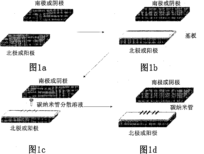
[0058] Example 3: Dispersing Magnetic Particles-Carbon Nanotubes on a Substrate

[0059] 5 mg of magnetic particle-carbon nanotubes prepared in Example 2 were dispersed in 50 ml of dimethylformamide (DMF), and then 10 ml of the dispersion was diluted in 40 ml of pure dimethylformamide (DMF).

[0060] Meanwhile, indium tin oxide (ITO) glass was fixed to a magnet with a magnetic field strength of 1000 Gauss, and placed in an oven at 120°C. When the temperature of the indium tin oxide (ITO) glass was raised to 120°C, 1 μl of the above solution of carbon nanotubes combined with magnetic particles diluted in dimethylformamide was dropped on the indium tin oxide (ITO) glass in the oven. ) on the glass and kept at 120° C. for 10 minutes to evaporate the dimethylformamide (DMF).


PUM

PropertyMeasurementUnit
thicknessaaaaaaaaaa

Abstract

The present invention relates to a method for fabricating a field emitter electrode, in which carbon nanotubes (CNTs) are aligned in the direction of a generated magnetic field. Specifically, the method comprises the steps of dispersing a solution of carbon nanotubes (CNTs) diluted in a solvent, on a substrate fixed to the upper part of an electromagnetic field generator, and fixing the carbon nanotubes aligned in the direction of an electromagnetic field generated from the electromagnetic field generator. According to the disclosed method, high-density and high-capacity carbon nanotubes aligned in the direction of a generated electromagnetic field can be fabricated in a simple process and can be applied as positive electrode materials for field emission displays (FEDs), sensors, electrodes, backlights and the like.

Description

technical field [0001] The present invention relates to a method of manufacturing a field emission electrode in which carbon nanotubes (CNTs) are aligned in a direction to generate an electromagnetic field. More specifically, the present invention relates to a method of manufacturing a field emission electrode comprising carbon nanotubes (CNTs) arranged in a direction in which an electromagnetic field is generated, the method comprising the steps of, on a substrate fixed to an upper portion of an electromagnetic field generator, The carbon nanotube (CNT) solution diluted in the solvent is dispersed, and the carbon nanotubes arranged in the direction of the electromagnetic field generated by the electromagnetic field generator are fixed. Background technique [0002] In general, a field emission device is a light source that is based on electron emission in a vacuum and involves an element that emits light using the principle that particles accelerated by a strong electric fi...

Claims


Application Information

Patent Timeline
Patent Type & Authority Patents(China)
IPC IPC(8): H01J9/02
CPCB82Y40/00C01B2202/08H01J1/304H01J9/025H01J2201/30469
Inventor 郑喜台尹相天高永观
Owner KOREA ADVANCED INST OF SCI & TECH
Why Eureka
Try Eureka