An organic EL part

An electroluminescence device and electroluminescence technology, which are applied in electroluminescence light sources, electric solid state devices, electric light sources, etc., can solve the problems of poor color stability, complicated implementation, and lack of chromatic white light for devices, and achieve luminous efficiency. Enhanced, improved chromaticity stability, high luminous efficiency and effect of color stability

Active Publication Date: 2007-11-28
TSINGHUA UNIV +1
View PDF0 Cites 9 Cited by
  • Summary
  • Abstract
  • Description
  • Claims
  • Application Information

AI Technical Summary

Problems solved by technology

However, in white light devices with these structures, since the energy bandgap of material molecules that can emit long-wavelength light is usually relatively narrow, its molecules are easy to capture holes and electrons are easy to inject into its molecules, resulting in more electrons. It recombines with holes on its molecules to form excitons, which reduces the number of carriers injected into the blue layer and the probability of carriers forming excitons, which can easily lead to the luminous intensity of long-wavelength materials at low voltages being lower than that of blue light. The luminous intensity of the device is relatively strong, so the device cannot obtain white light with pure chromaticity under low voltage. Overall, the color coordinate of the device changes greatly with the driving voltage, resulting in poor color stability.
This problem can be better solved by changing the thickness of the light-emitting layer and the doping ratio, but it is more complicated to implement.

Method used


Image

  • An organic EL part
  • An organic EL part
  • An organic EL part

Examples


Embodiment 1-3

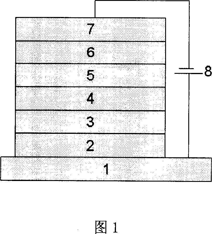
[0057] Three OLEDs were prepared in the same manner as the device shown in formula (1) above. The structure of the three OLEDs is shown in Table 1 below, and the performance data of the device under the driving voltage of 5V is shown in the table below.

[0058] Example 1

[0059] It can be seen from Table 1 that under the experimental conditions of the present invention, when the thickness of the electron buffer layer is 3nm, the device can obtain white light with relatively good chromaticity when the driving voltage is 5.

Embodiment 4-6

[0061] Three OLEDs were prepared in the same manner as the device shown in formula (1) above. The structure of the three OLEDs is shown in Table 1 below, and the performance data of the device under the driving voltage of 5V is shown in the table below.

[0062] Example 1

[0063] It can be seen from Table 1 that under the experimental conditions of the present invention, when the thickness of the electron buffer layer is 2nm, the device can obtain white light with relatively good chromaticity when the driving voltage is 5.

Embodiment 7-9

[0065] Three OLEDs were prepared in the same manner as the device shown in formula (3) above. The structure of the three OLEDs is shown in Table 3 below, and the performance data of the device under the driving voltage of 5V is shown in the table below.

[0066] Example 1

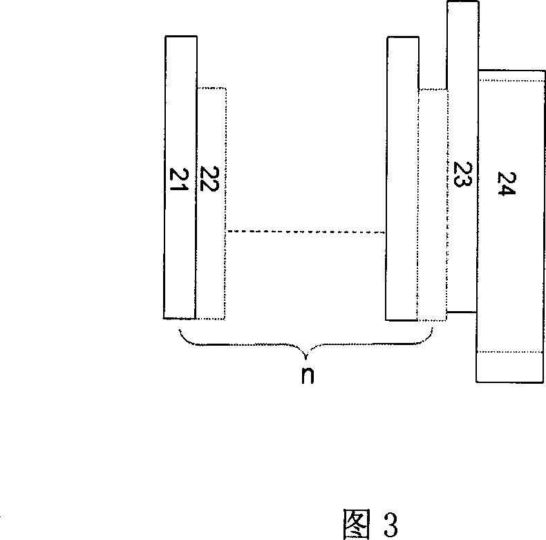
[0067]It can be seen from Table 2 that under the experimental conditions of the present invention, when the quantum well period number n is 4, the overall performance of the device is the best.


PUM


Abstract

The invention discloses an organic electroluminescent element, which contains electron buffer layer in the organic functional layer between cavity transmitting layer and luminous layer; the electronic buffer layer possesses higher lowest molecular occupying track and maximum molecular occupying track near the cavity transmitting layer material, which is made of the material to transmit cavity and also buffer partial electron with white color under low pressure and higher color stability.

Description

technical field [0001] The invention relates to an organic electroluminescence device, more specifically, the invention relates to a high-efficiency organic electroluminescence device which can obtain white light with better chromaticity and good color stability under low pressure. Background technique [0002] Today, with the development of multimedia technology and the advent of the information society, the requirements for the performance of flat panel displays are getting higher and higher. In recent years, three new display technologies: plasma display, field emission display and organic electroluminescent display have made up for the shortcomings of cathode ray tubes and liquid crystal displays to a certain extent. Among them, organic electroluminescent displays have a series of advantages such as self-luminescence, low-voltage DC drive, full curing, wide viewing angle, and rich colors, which are 1000 times that of liquid crystal displays, but their manufacturing costs...

Claims


Application Information

Patent Timeline
Patent Type & Authority Applications(China)
IPC IPC(8): H01L51/50H05B33/12
Inventor 邱勇吴空物段炼高裕弟张德强
Owner TSINGHUA UNIV
Why Eureka
Try Eureka