Method for restraining complicated ingredient noise in ultrasound detection signal

An ultrasonic detection and signal technology, applied in the direction of processing the response signal of detection, can solve the problems of poor signal noise suppression effect and complex component noise, and achieve good noise suppression effect, more robustness, and strong adaptability.

Inactive Publication Date: 2007-12-05
HARBIN INST OF TECH
View PDF0 Cites 12 Cited by
  • Summary
  • Abstract
  • Description
  • Claims
  • Application Information

AI Technical Summary

Problems solved by technology

[0011] In order to solve the problem of poor signal noise suppression effect in the existing ultrasonic detection signal noise suppression technology, the pre

Method used


Image

  • Method for restraining complicated ingredient noise in ultrasound detection signal
  • Method for restraining complicated ingredient noise in ultrasound detection signal
  • Method for restraining complicated ingredient noise in ultrasound detection signal

Examples


specific Embodiment approach 1

[0022] Specific implementation mode one: this implementation mode is completed by the following steps:

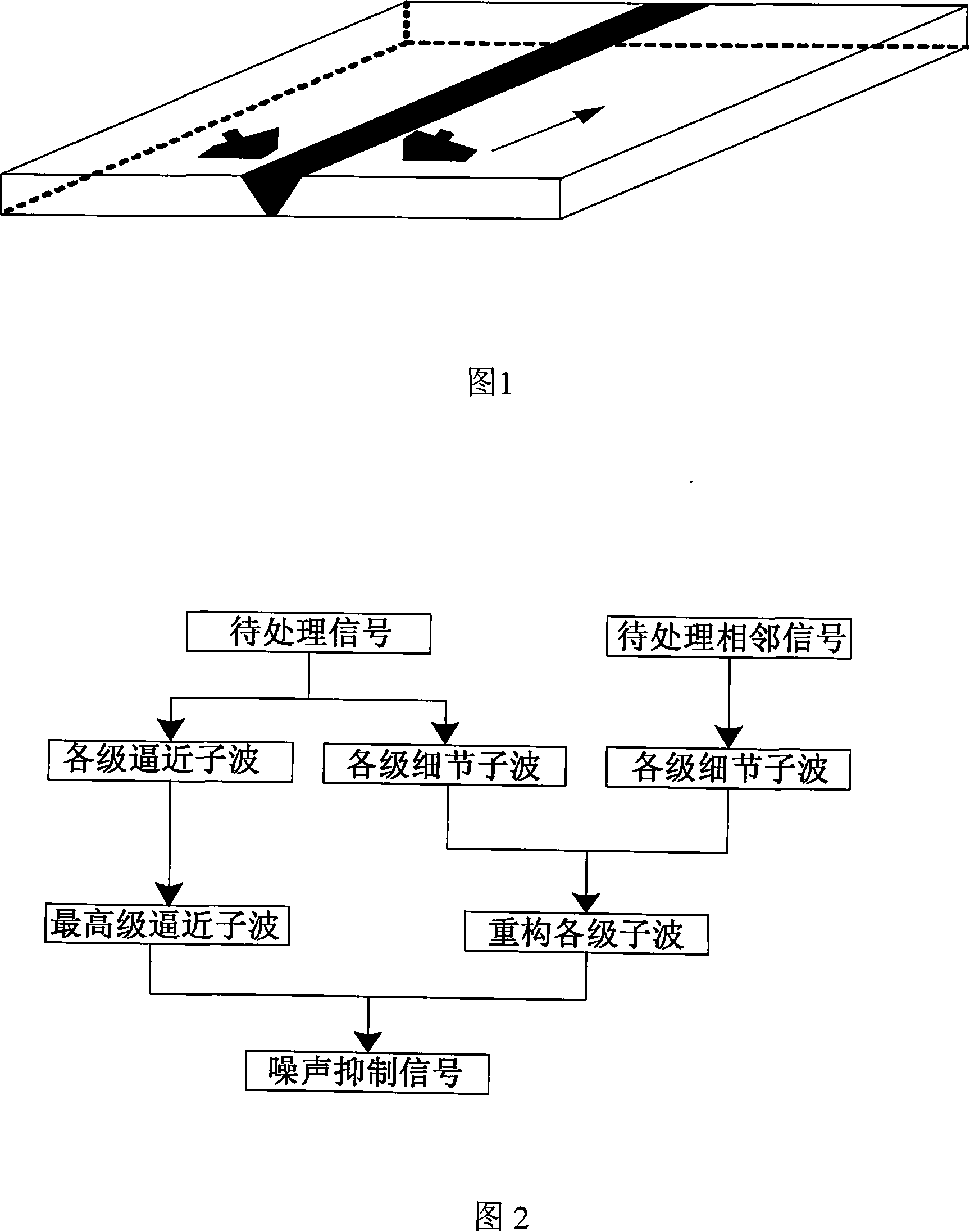
[0023] Step 1: Obtain a detection D-scan image; remove the lateral wave in the detection D-scan image;

[0024] Step 2: Select the mother wavelet and determine the level of decomposition, perform wavelet decomposition of the one-dimensional signal on the A-scan signal in the D-scan image obtained in step 1, and obtain detail wavelets and approximation wavelets at all levels after decomposition;

[0025] Step 3: Select the same mother wavelet and decomposition level as in the previous step for the adjacent signal of the A-scan signal to be processed in the previous step, perform wavelet decomposition of the one-dimensional signal, and obtain detail wavelets and approximations at all levels after decomposition wavelet;

[0026] Step 4: Perform cumulative multiplication operations on the decomposed detail wavelets of the A-scan signal to be processed and its adjacent signals ...

specific Embodiment approach 2

[0033] Specific implementation mode two: the following specific description of this implementation mode, this implementation mode takes the aluminum alloy weld seam as the detection object:

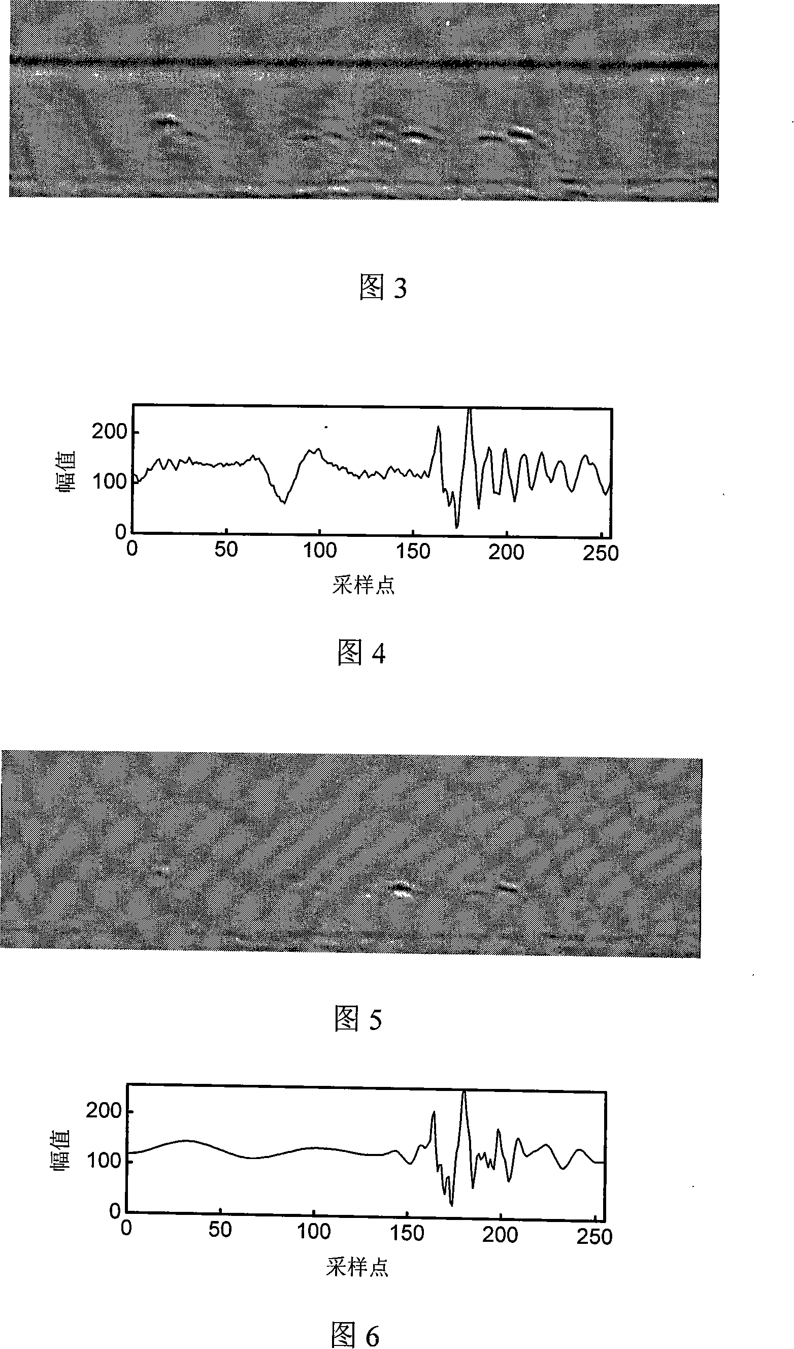
[0034] Step 1: Arrange the probes on the aluminum alloy weld seam of the thick plate to be tested as shown in Figure 1, and the distance between the two probes is 50mm. The system gain is 68dB, the sampling frequency is 100MHz, the system scanning length is 180mm, and the scanning step is 0.2mm. A total of 900 columns of A-scan signals were obtained, and arranged in sequence to form a D-scan digital image, as shown in Figure 3, corresponding to the 214th column of A-scan signals as shown in Figure 4, and the size of the digital matrix is ​​256×900; adaptive filtering technology is used to detect D-scan The lateral wave in the scanned image is removed;

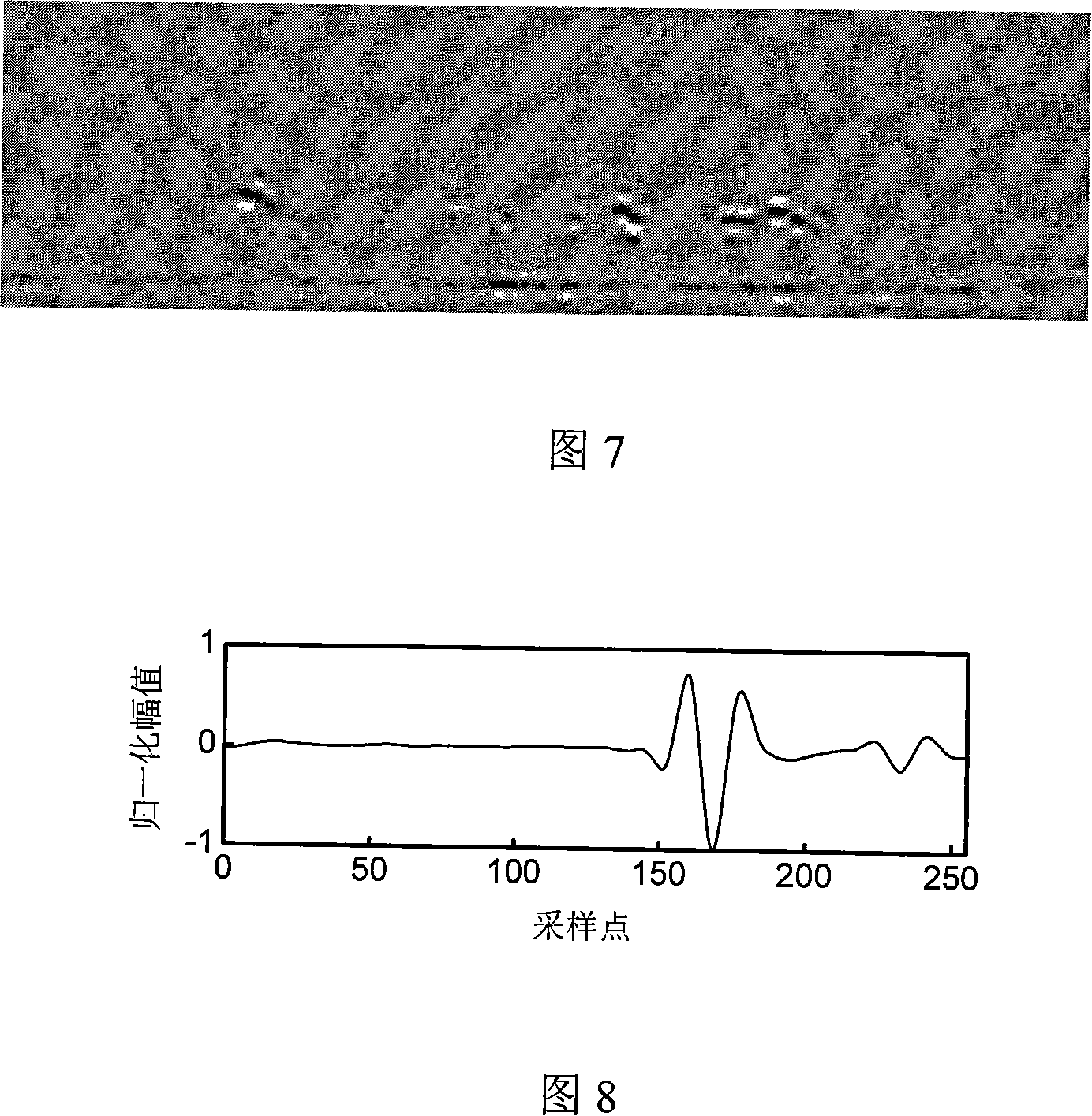
[0035] Step 2: Perform noise suppression processing one by one on the A-scan signals in the D-scan images after the side waves have been...


PUM


Abstract

The invention discloses an inhibiting method of complex component noise in the ultrasonic detecting signal in the non-destroying testing domain of ultrasound, which comprises the following steps: adjusting the parameter of the testing system to obtain the D scanning image through ultrasonic TOFD method; removing lateral wave in the D scanning image; proceeding one-dimension small-wave decomposition for the disposed A scanning signal and adjacent signal of the D scanning image without lateral wave; multiplying each grade detail wavelet of two signals to obtain new detail wavelet; reconstructing one-dimension small wave for each grade detail wavelet after the threshold value is disposed and the highest grade approximate wavelet of the disposed A scanning signal; obtaining the noise inhibited A scanning signal; disposing each row of A scanning signal to reconstruct D scanning image. The invention possesses strong adaptability to inhibit complex component noise in the signal, which has more robustness for the disposing result of different small waves.

Description

technical field [0001] The invention belongs to the field of ultrasonic non-destructive testing, in particular to a method for suppressing complex component noise in ultrasonic testing signals. Background technique [0002] Ultrasonic Time of Flight Diffraction, referred to as ultrasonic TOFD (Time of Flight Diffraction), is a detection method based on receiving the diffraction signal at the end of the defect to locate and quantify the defect, and is a relatively new ultrasonic detection method. As shown in Figure 1, on the entire scanning line of the D-scan of the ultrasonic transit time diffraction method, the ultrasonic probe works in the manner of "scanning-sampling-scanning". The D-scan image is sequentially arranged by the A-scan signals acquired by the probe at different scanning positions, and the A-scan signal data can be read from the D-scan image data. Compared with the reflection signal, due to the weak intensity of the diffraction signal, the system needs to wo...

Claims


Application Information

Patent Timeline
IPC IPC(8): G01N29/44
Inventor 刚铁迟大钊盛朝阳
Owner HARBIN INST OF TECH
Why Eureka
Try Eureka